Introduction
The Storno 5000 has a red LED on the RF (bottom) board which is the TX led. However, once the selcall board is removed as part of the other modifications described on this site, there is no way to see when the squelch is open.
I decided that I would remedy this by replacing the red TX led with a bicoloured 5mm red/green LED, with red for TX and green for RX (squelch open).
Details
In order to replace the red TX led, you need to remove the RF board from the radio. I’d recommend following the instructions here: Storno 5000 dismantling Note that you do not need to remove the synthesizer board from the radio, though you will need to remove the front panel.
Replacing the LED
Desolder and remove the red LED and replace it with two pins of your three-legged bicoloured LED. Check the pinout to ensure that you connect the correct two legs to ensure it will light up red on TX still. Leave the third leg (green anode) loose at this point.
Replace the RF board into the radio, replace the nuts anchoring the power transistors to the chassis and refit the synthesiser board. Check that the radio still functions as expected and that keying the radio should cause the LED to light up red.
Connecting up the green anode to the squelch-open signal
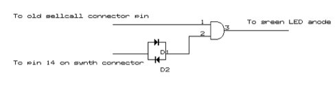
This is slightly complicated, because I haven’t managed to find a proper ‘squelch open’ signal. There are two signals which need to be AND’ed together to get a meaningful squelch open signal.
These are: Pin 14 of the synth connector is high when the radio is on RX, regardless of whether the squelch is open or not.
A pin on the selcall board connector, which is high when the radio is on TX *and* when the squelch is open.
So, AND-ing these two signals together gives the desired logic for the squelch LED. I used a 4081 AND gate IC powered off the 5v supply that is described as part of the Storno 100-channel modification.
The pinout of the 4081 is as follows:
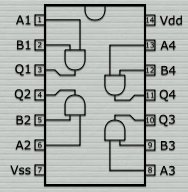
5V should be applied to Vdd (pin 14) GND should be applied to VSS (pin 7)
The circuit uses the first gate, pins 1, 2 and 3. The datasheet recommends all the other pins (unused gates) be connected together and grounded.
The two diodes (D1 and D2) just need to be simple silicon diodes such as 1N4148.
Pin 14 on the synth connector is as follows: (far right)
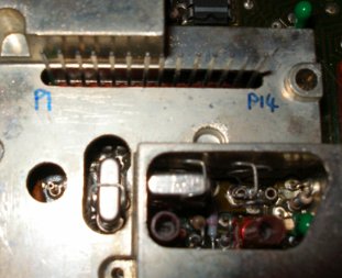
If you build the other mods as suggested, this signal will already be available on the veroboard, as it is the PTT line.
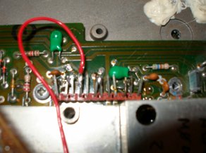
The selcall connector is on the left hand side of the synth board. The red wire shown below is connected to the correct pin (the fourth from the front).
The wire to the anode of the green LED can be run behind the front panel through to the lower half of the radio, and then connected to the LED.