Introduction
The standard way to install a toneburst board is to use the Call button on the front panel to key the radio into transmit and send the tone. However, most Taits are not set up to key the radio into Tx when the button is pressed.
Step 1
The first step is to make the Call button key the radio into Tx mode. This is accomplished by cutting a track around the switch on the PCB and soldering in a wire, which will join one of the switch contacts to the TX line of the radio. The six pads visible are those of the switch. The switch is a dual gang, two way switch.
Both gangs of the switch are joined together at the top two pins by a small track running between them. For correct operation of the toneburst, it is necessary to cut the track with a tool such as a small scalpel. You can see on the photograph where this has been done. Once this is done, a small (insulated!) wire should be connected between the top left hand switch contact and a convenient solder pad somewhere along the radio TX line. Ensure you are soldering to the correct pad by checking to see that it is grounded when keying the microphone. The photograph below shows my T535 after completion of Step 1 (red wire is the one added)

Step 2
The next step is to build a toneburst circuit small enough to fit into the radio. I used a design by Andy Potts, the layout of which is reproduced below, with his permission. His website is available here

This design does not have any provision for frequency adjustment – this is because the frequency is crystal controlled, and is extremely accurate (even accurate enough to open my ‘home’ repeater, GB3SR, which is notoriously picky about such things!)
I built my toneboard on a piece of veroboard, and with careful use of space, it is possible to fit the circuit onto a piece about 1sq inch in size. Note: You should use an edge track as your ground rail – you will see why shortly!
There are two components used in the circuit which can be challenging to locate can be obtained from the following UK suppliers:
7.168MHz Crystal from QuartsLab UK
TC5082P IC from Telepart
Don’t be put off from building this circuit by the word ‘crystal’ – these ones are cheap and readily available.
Before installing the board, power it up, connect an earpiece/speaker, ground the activation wire and see if a tone is produced. If not, check your circuit for shorts and wiring errors. I found the circuit was very reliable in use, and the only problems I’ve encountered were due to mis-assembly etc!
Step 3
The final step is to install the module into your Tait. I found that the best way to fit the toneboard is to affix it to the CTCSS module, as the CTCSS board has the necessary points on it (12V DC, and a channel into the rig’s audio circuitry).
I attached mine by soldering my ground rail of the veroboard to the ground plane of the CTCSS board thus joining the two together. (Now you know why I suggested using an edge track as a ground rail). Attach a small piece of insulating tape or sticky foam to the back of your toneburst board to prevent it from shorting on anything when the radio is reassembled.
The photo below shows the modified toneboard:
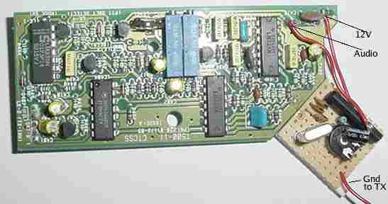
The only wire left to attach to make the tone board operational is the Gnd to Tx wire. This should be attached to the unused gang of the Tone switch on the front panel. If you follow the track from the unused gang, it passes through a plated through hole on to the upper side of the board. Soldering the wire to the plated through hole is the simplest way to complete this modification.
The final thing to do is to adjust the deviation of the 1750Hz tone. This can be done using the trimmer in the circuit.
Also, it is important to note that the CTCSS deviation trimmer on the CTCSS board itself affects the deviation of the 1750Hz circuit
As the two interact, it will be necessary to take some time to find satisfactory settings so both the 1750Hz tone and the CTCSS tones operate at suitable deviation levels.
Troubleshooting
Every time I transmit, I get a tone, even when using the Microphone PTT switch
Check you cut the track between the upper two contacts of the tone switch. If these are not separated, the PTT Line will ground your 1750Hz activation line and send a tone anyway.
The board was working fine before I installed it, but now I’ve fitted it, it seems to have died.
Try adjusting the CTCSS deviation trimmer on the CTCSS module, as this can stop your tone circuit oscillating if in certain positions. (minimum deviation setting causes problems)