NB: If I was doing this now, I’d do it with a microcontroller, and not with EEPROMS. But for nostalgia, here are the original instructions:
Introduction
I found the two channels the Tait diode board provided too limiting for my planned use of the set, so I decided to try something else. A small amount of ‘panel bashing’ was needed to complete it, cutting a small square out of the plastic front panel and the metal plating behind it to fit the thumbswitches used to select the channel.
The end result:
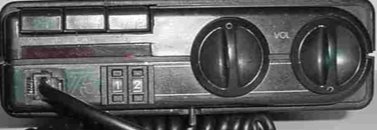
(This photograph also shows the microphone socket installation modification too)
Files needed
Click to download:
Tait EEPROM image A (S3F format)
Tait EEPROM image B (S3F format)
Tait channel list
Circuit diagram
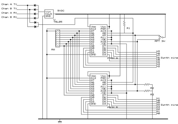
The Tait synth requires a 16 bit input to set the frequency, so I decided to use two 8-bit eproms, with the address lines all connected together, with Prom A supplying the top 8 bits of the frequency data, and Prom B supplying the bottom. There are four signal inputs which were used by the original diode matrix – they are high (8V) normally, going to 0V when that particular channel/(RX/TX) combination is selected. By using four diodes, as three are 8V high at any one time, they can be used as a source of power to power the board. These are fed into a 78L05 low-current 5VDC output regulator to provide a regulated power source for the circuit. The TX/RX switching is accomplished via EPROM address line 8, via a pair of diodes (note polarity) on both Chan A/Chan B TX line.
The channel switch is not used in the mod at present, so using both chan lines ensures the EPROM address will be changed whichever channel is ‘selected’ on the front panel. A separate SPDT latching switch (centre off) was used for the repeater shift, and was fitted under the front panel, where the original microphone cable came out. If you leave the microphone hardwired, you will need to find somewhere else to mount the repeater switch. A9 (when high) provides -600kHz repeater shift, whereas A10 provides reverse repeater shift (aka ‘listen on input’)
The connections to the thumbswitches are not shown on the above diagram for reasons of clarity.
They are as follows:
A7 8’s of ‘tens’ thumbwheel
A6 4’s of ‘tens’ thumbwheel
A5 2’s of ‘tens’ thumbwheel
A4 1’s of ‘tens’ thumbwheel
A3 8’s of ‘units’ thumbwheel
A2 4’s of ‘units’ thumbwheel
A1 2’s of ‘units’ thumbwheel
A0 1’s of ‘units’ thumbwheel
Parts list
R1, R2, R3: 10k resistors
RA: 8-way 10k resistor array
Diodes; IN4148 or similar silicon diodes
Prom A/Prom B: 27C128 (you can use 27C258, same pinout, but program the upper half of the chip)
2x decimal thumbswitches
Eeprom images in S3F format are available to download from the main T500 page here
Pinouts of the diode matrix board pins
| x – Channel A (Gnd to TX) | |
| x – Channel B (Gnd to TX) | |
| x – Channel A (Gnd to RX) | |
| x – Channel B (Gnd to RX) | |
| x – N9 | |
| x – N8 | |
| x – N7 | |
| x – N6 | x – A5 |
| x – N5 | x – N0 |
| x – N4 | x – N1 |
| x – Gnd | x – N2 |
| x – | x – N3 |
| x – Gnd if C1 (C1 LED) | x – A1 |
| x – Gnd if C2 (C2 LED) | x – A2 |
| x | x – A0 |
| x – 1.8V if squelch open | x – A3 |
| x | x – A4 |
| x – 1.75V (Channel LED Constant supply) |
Note: Synth data lines (N9 -> A0) are pulled UP to CMOS levels (8V) internally, rather than pulled DOWN to GND. However, it’s only a signal voltage, so a TTL EPROM (or pair of 8bit ones!) has no problem pulling them down etc.
Note: The four diode lines connect to the top four pins on the left hand connector, detailed above.
Fitting hints
Open the radio, and remove the diode matrix board. You will need to remove the two connectors from it and solder them onto your board. Alternatively, you might choose to cut all the ‘output’ pins on the diode matrix board, and ‘piggy back’ your new board on top of it. If you choose this option, it saves the problems of trying to reconnect the LEDs on your board, which can be rather fiddly if you use veroboard.
Another space saving idea is that as the EPROMs share everything except their output data lines (D7-D0) is to piggy back the eeproms on top of each other – that is, to mount one on top of the other, bending the data line legs up, and soldering the ‘common’ legs together.
A few photos of my mod, on veroboard: Front of radio at bottom.
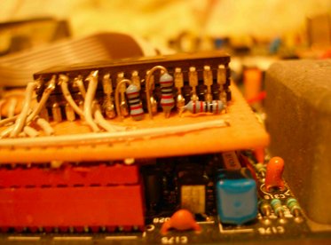
Piggyback proms: I know it’s not the neatest, but it does work, and in my defense, space was limited!
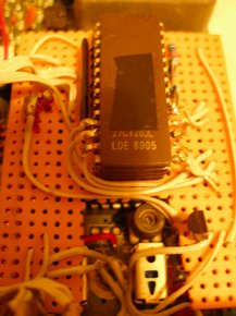
Next time I try this, I would rest my board on top of the diode matrix board, with a suitable insulator in between as it would save a bit on wiring, especially for the LEDs.