Introduction
Tools required
Fine point soldering iron (temperature controlled recommended)
Multimeter capable of measuring low- voltage DC (1-40v) – you will need this to set up the boost/buck converter boards
Nail varnish or similar – idea
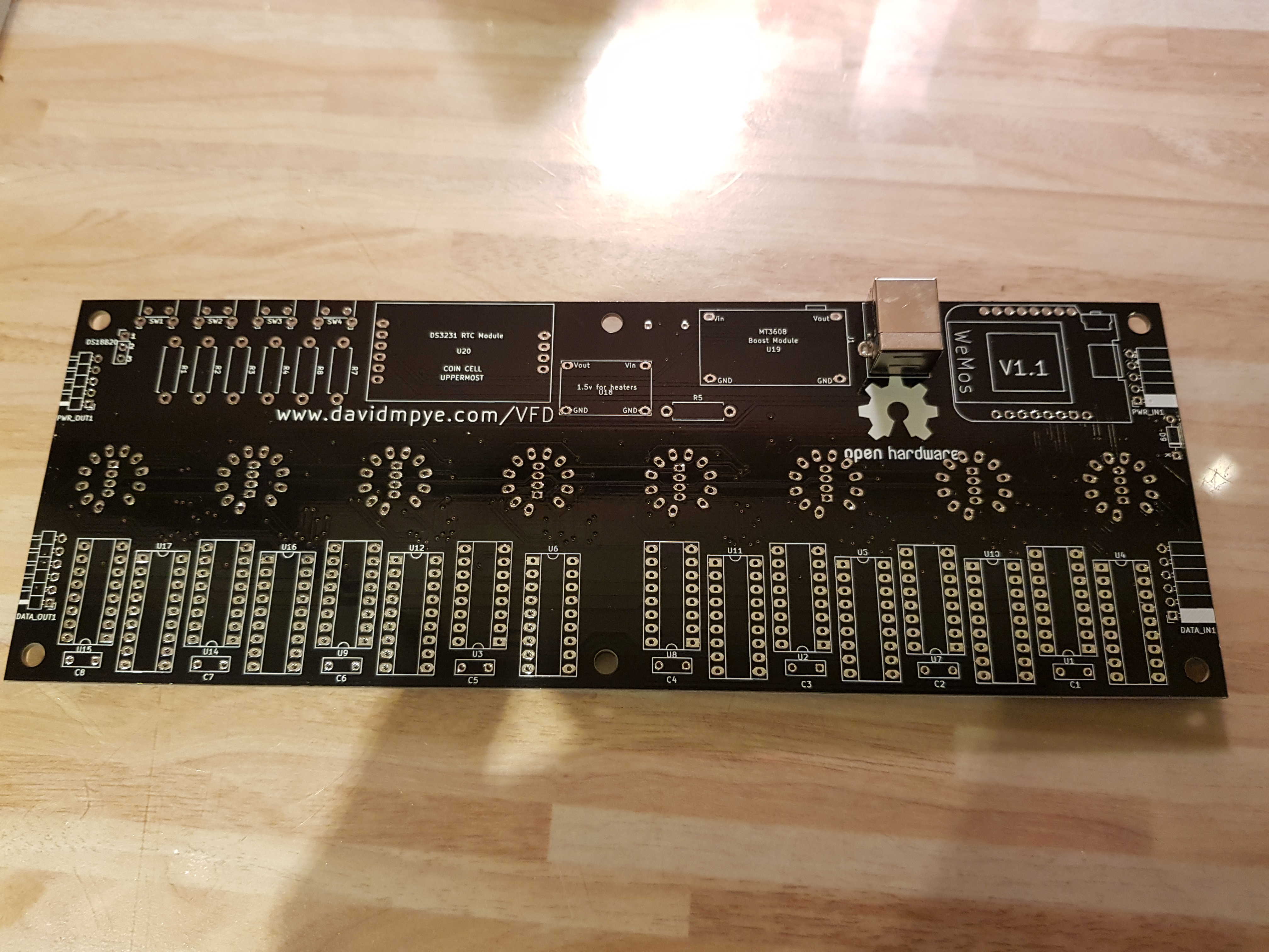
USB socket
Insert the USB B socket onto the LOWER side of the board, and solder its’ four data pins and two retaining lugs.
Programmable LEDs and IN4148 diode
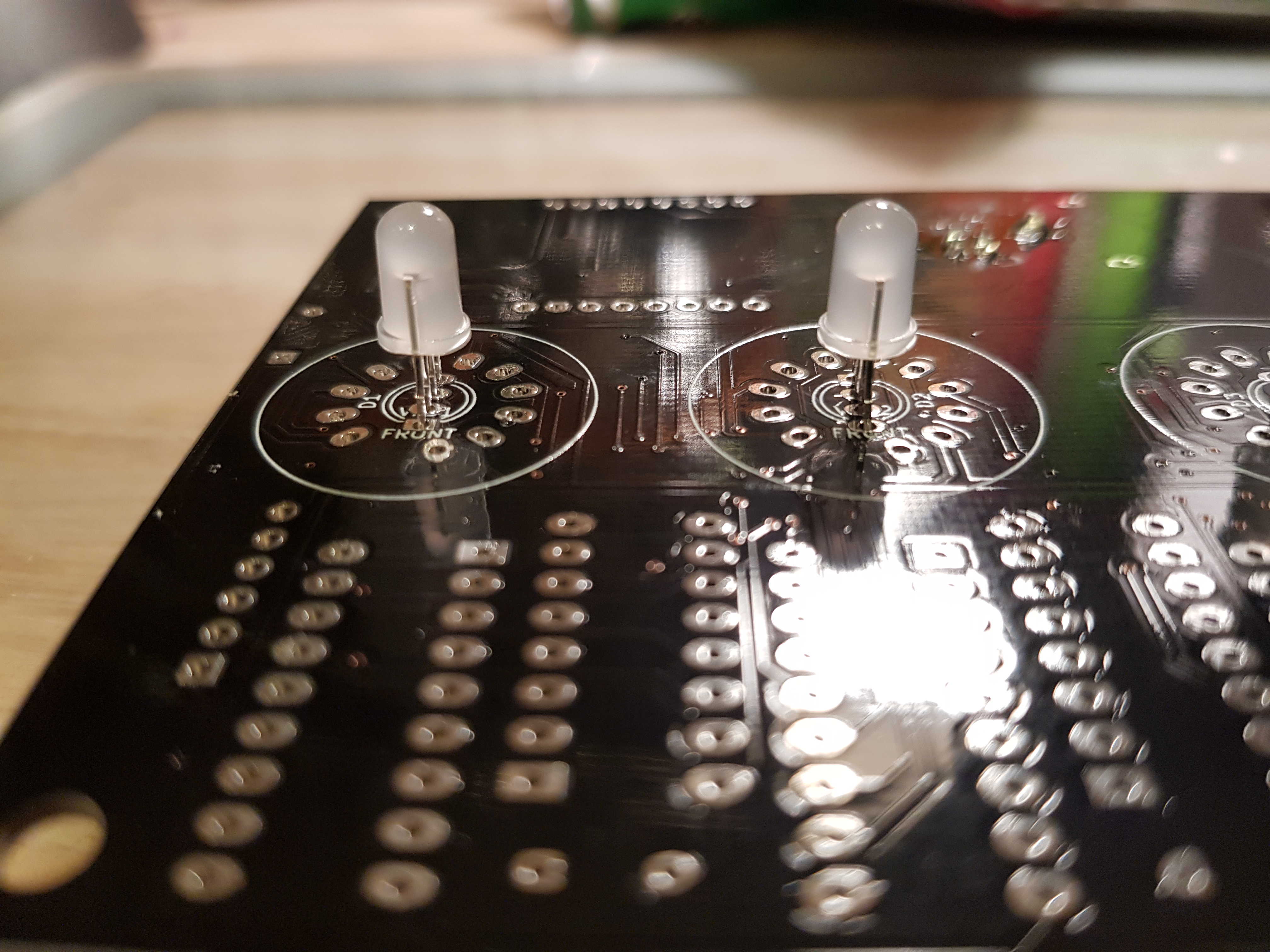
Install the programmable LEDs on the UPPER surface of the PCB. Note the polarity carefully, as shown below. Each LEDs’ polarity is ALTERNATED – be careful to get the LED orientation right. Try to get them as vertical as possible.
Don’t mount the LEDs flush with the surface of the PCB – leave a gap of around 4mm, as shown below:
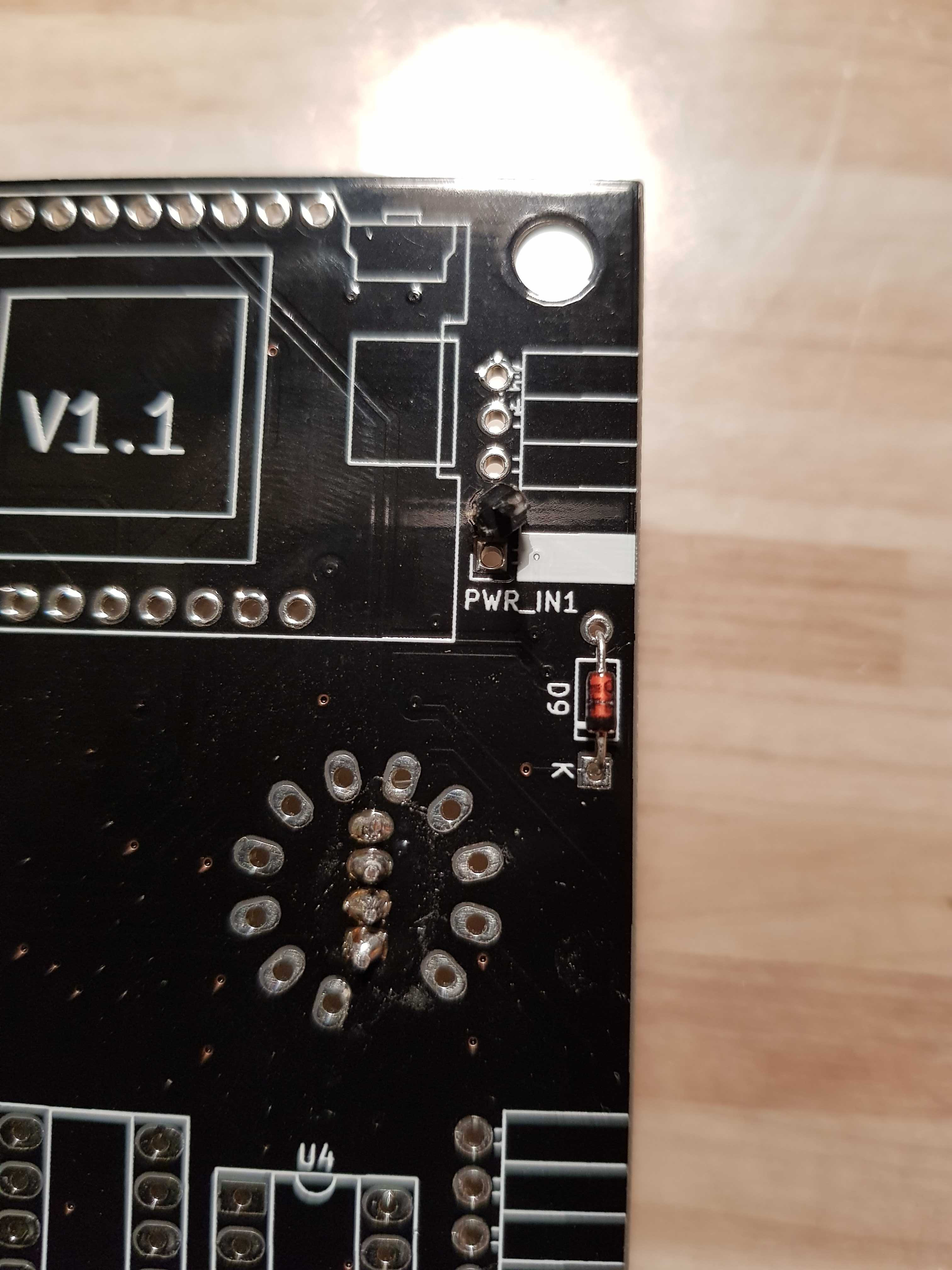
Next, insert the small signal diode on the LOWER side edge of the board, ensuring that the black line on its’ body faces the same way as the white line on the PCB silkscreen (photo below shows diode the right way round before laying flush with the board and soldering in to place.
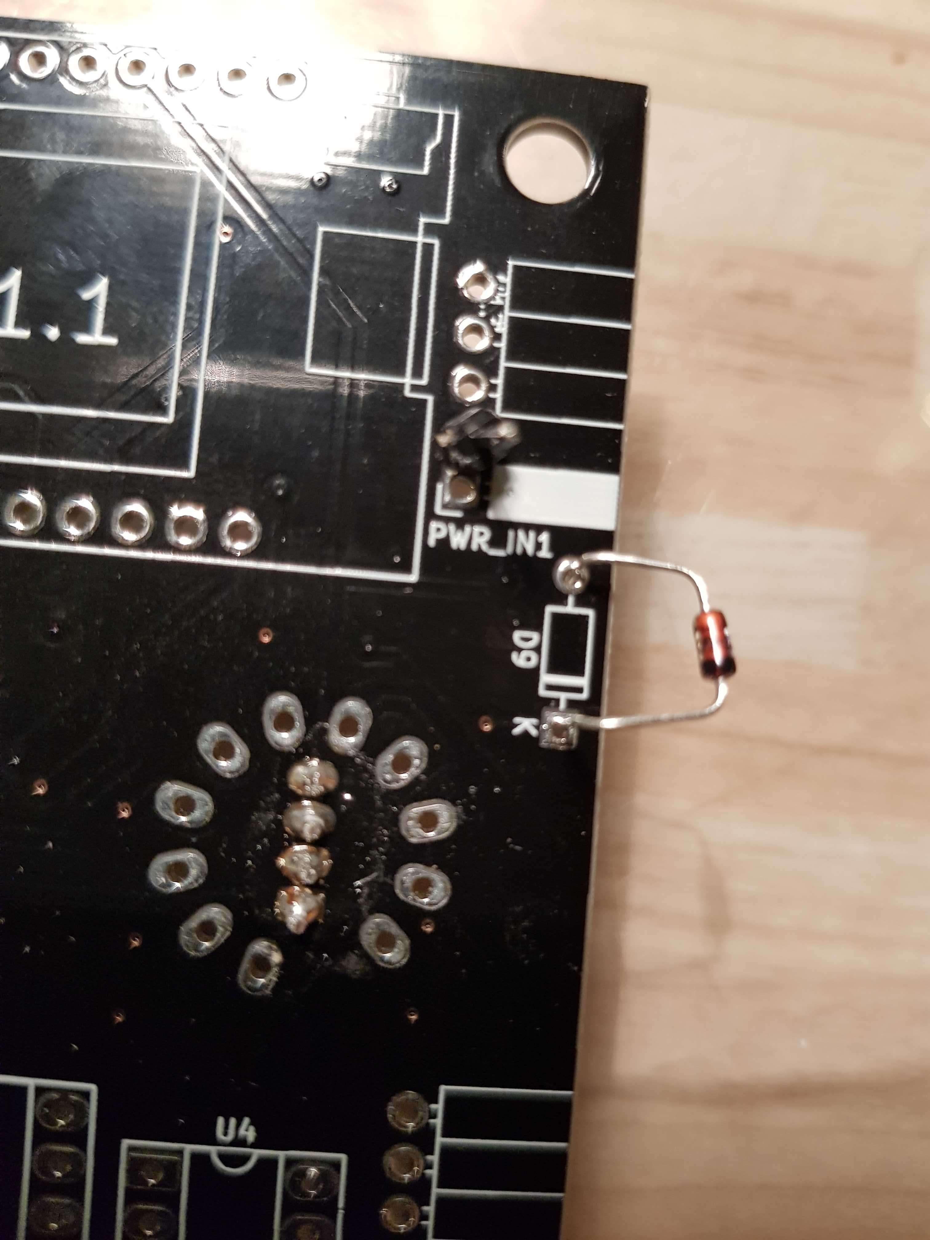
The diode correctly soldered into place:
At this point, connect a USB B cable to the USB socket, and plug in to a power source (either PC USB socket, or a USB adaptor etc). All the LEDs should light up blue.
Install 1.5v low voltage buck converter
Break off four individual pin headers from the pin header strip supplied, and solder them to the pin holes in the buck regulator board as shown below:
Then, install the converter onto the LOWER side of the PCB in the location marked 1.5v for headers U18. You may need to angle/bend the pins to line up with the board holes. Once inserted, solder the pins into place from the UPPER side of the board (shown in place below):
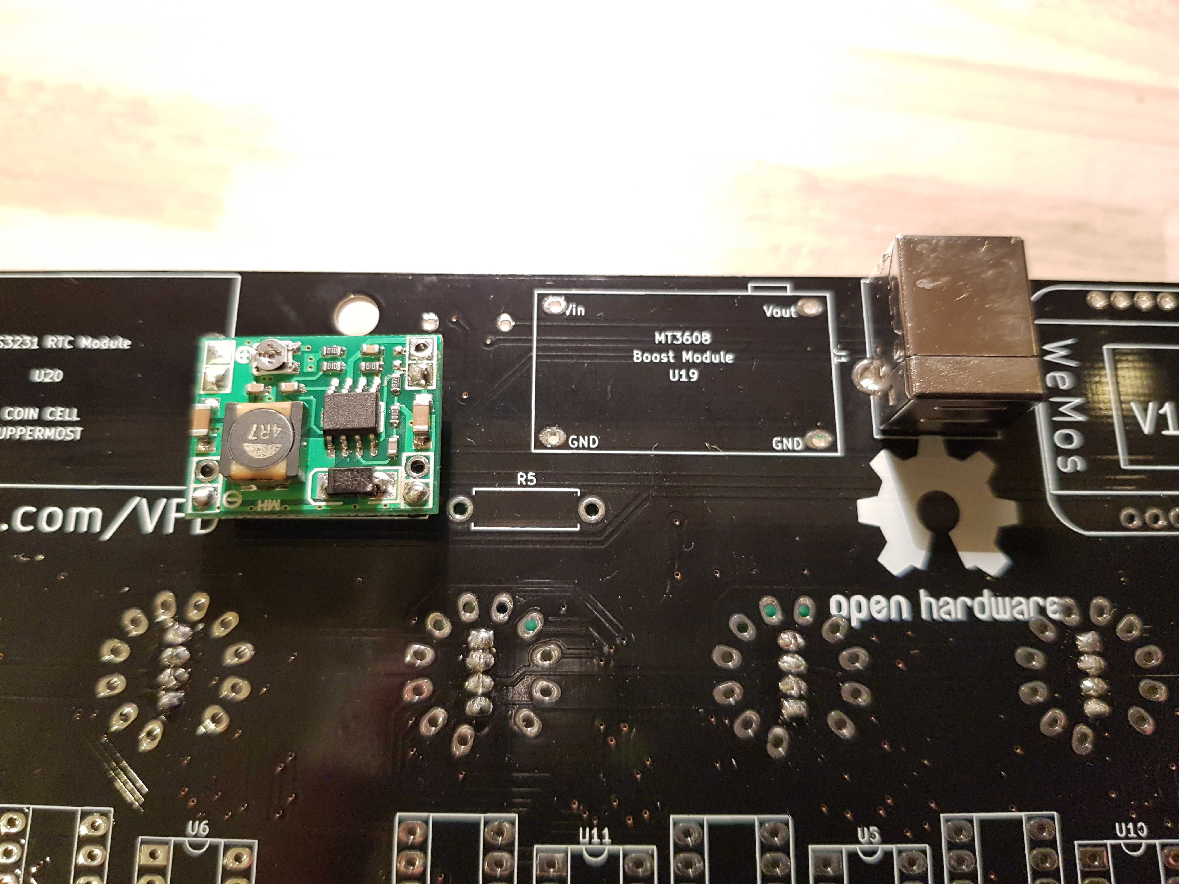
Install 25v high voltage boost converter
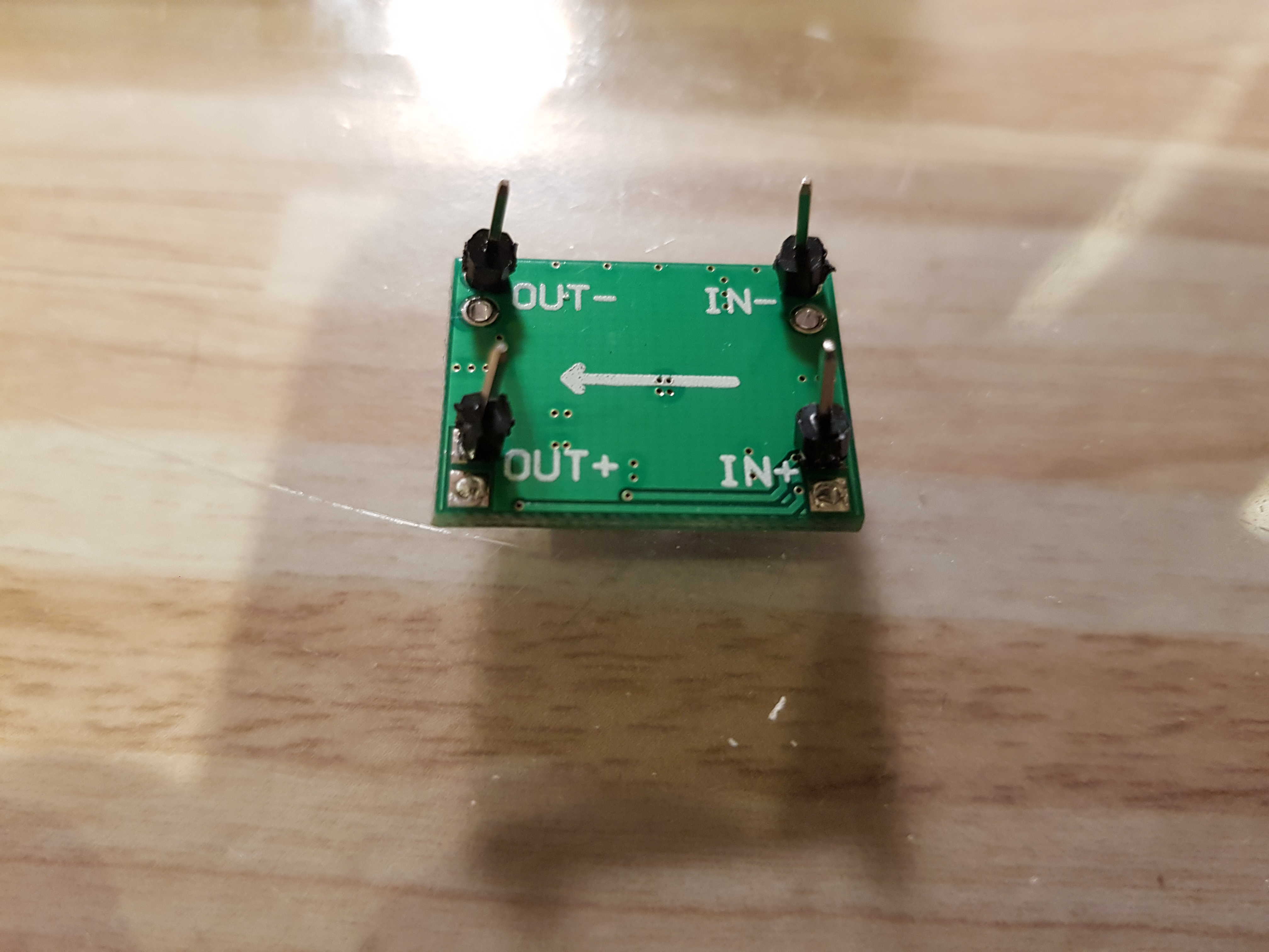
Solder four individual pins into the holes in the boost converter, then install it onto the board as shown below, and solder the other end of the pins in to place.
Setting the voltages
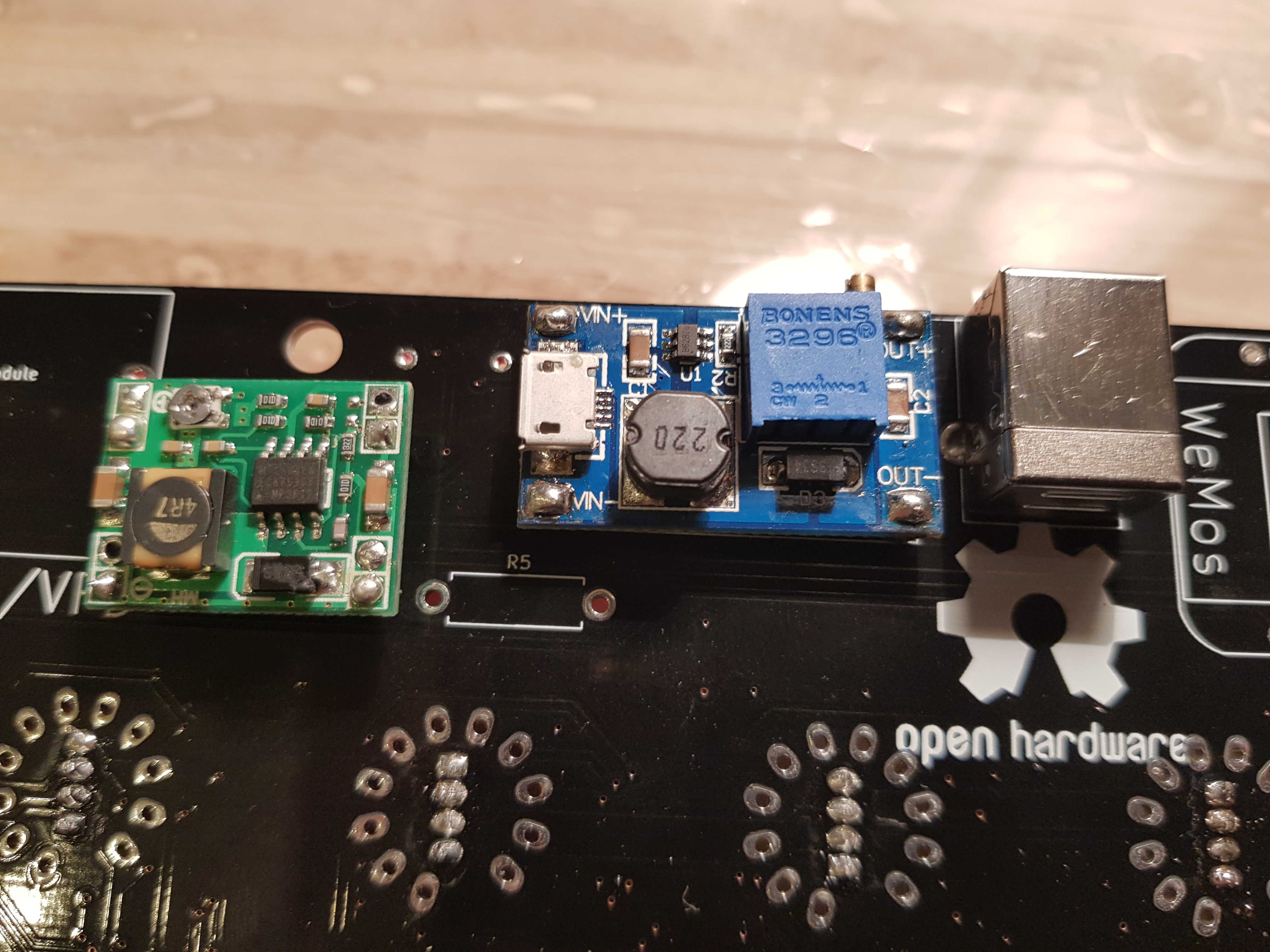
Next, apply 5V power to the USB-B socket, and use a multimeter and small potentiometer-adjustment screwdriver to set the voltages for the buck/boost converters.
For the boost (high voltage) converter, the gold screw on the blue potentiometer should be turned to set the voltage on its’ V-OUT pin to 25v.
For the buck converter, the potentiometer should be adjusted to get 1.5V (+/- 0.15V) on its’ V-OUT pin.
Once these potentiometers have been adjusted correctly, a small dot of nail varnish is useful to stop them from moving again.
Install the real-time clock module
Bend the 6 pins already installed into the RTC module so they point straight down (away from the board), and solder 4 pins from the supplied pin header strip into the four vacant holes at the other edge of the board, as shown below:
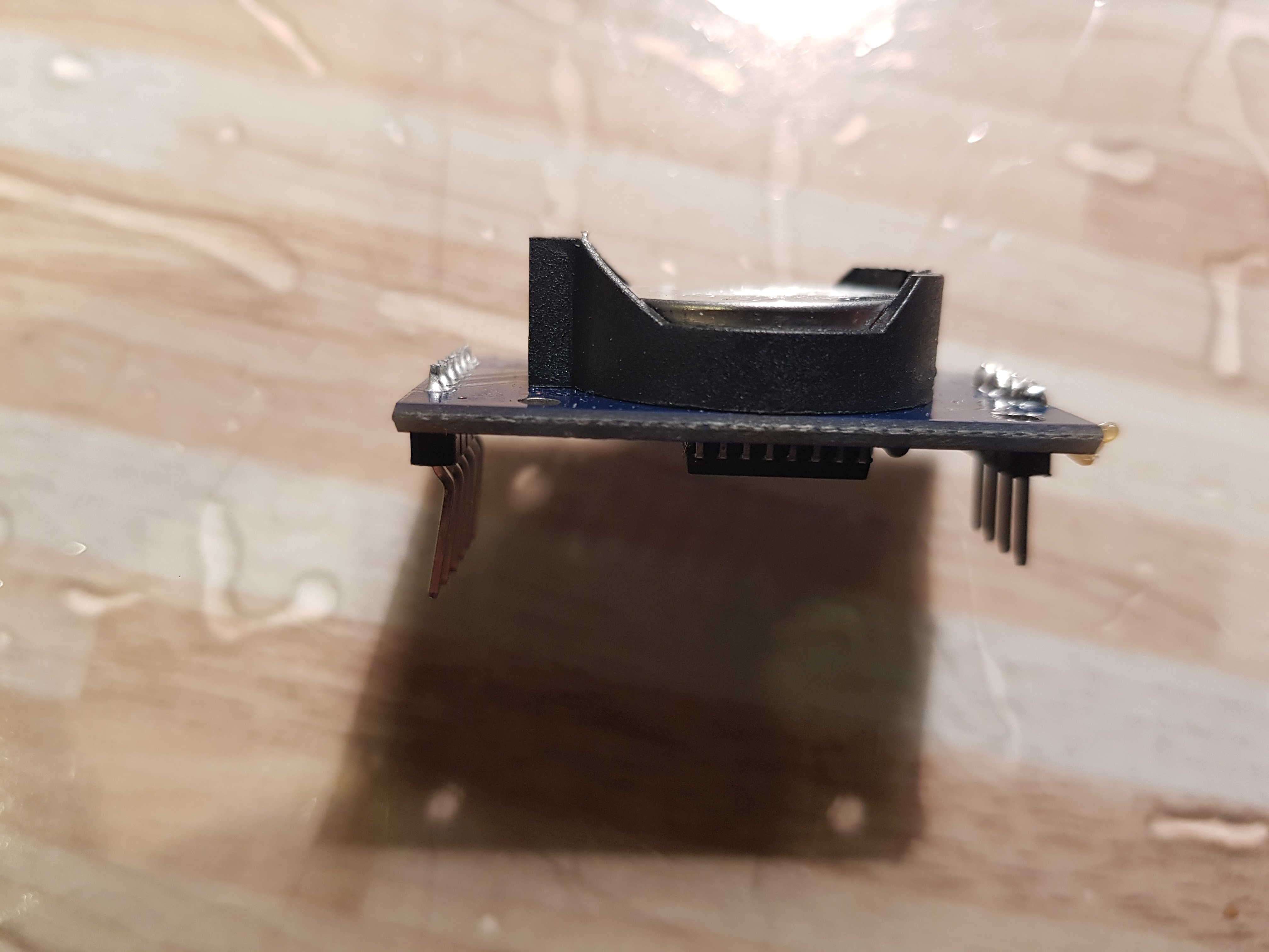
Then, install the RTC module and solder in to place:
Install the push switches and resistors
Insert the four pushbutton switches into place on the LOWER side of the board and solder them into place.
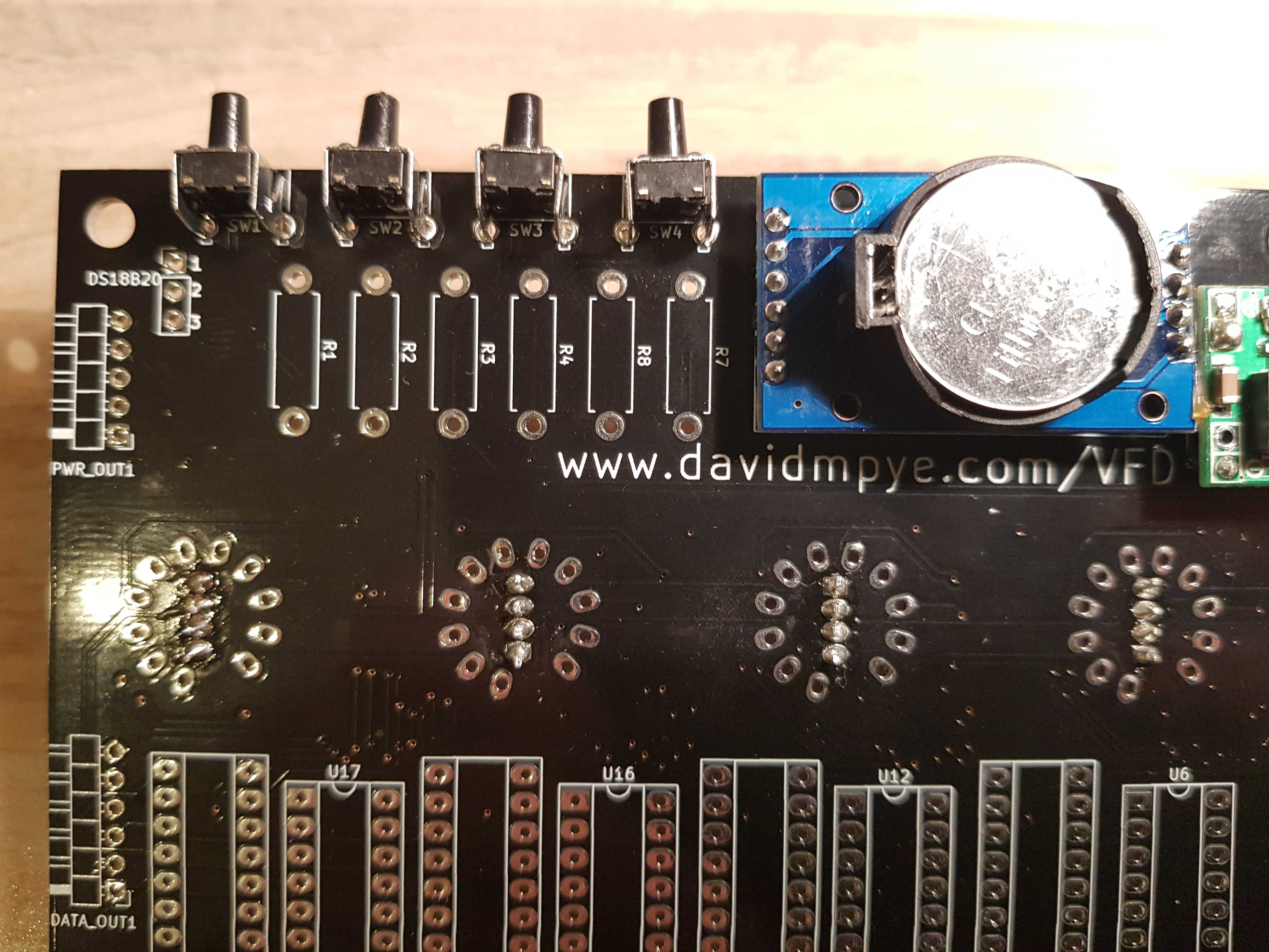
Then, install the resistors into place: (they can be installed either way round)
R1-R4 are 10K ohm resistors (colour code brown black orange gold)
R5 is a 22k ohm resistor. (colour code red red orange gold)
R7 and R8 are 4k7 ohm resistors. (colour code yellow violet red gold)
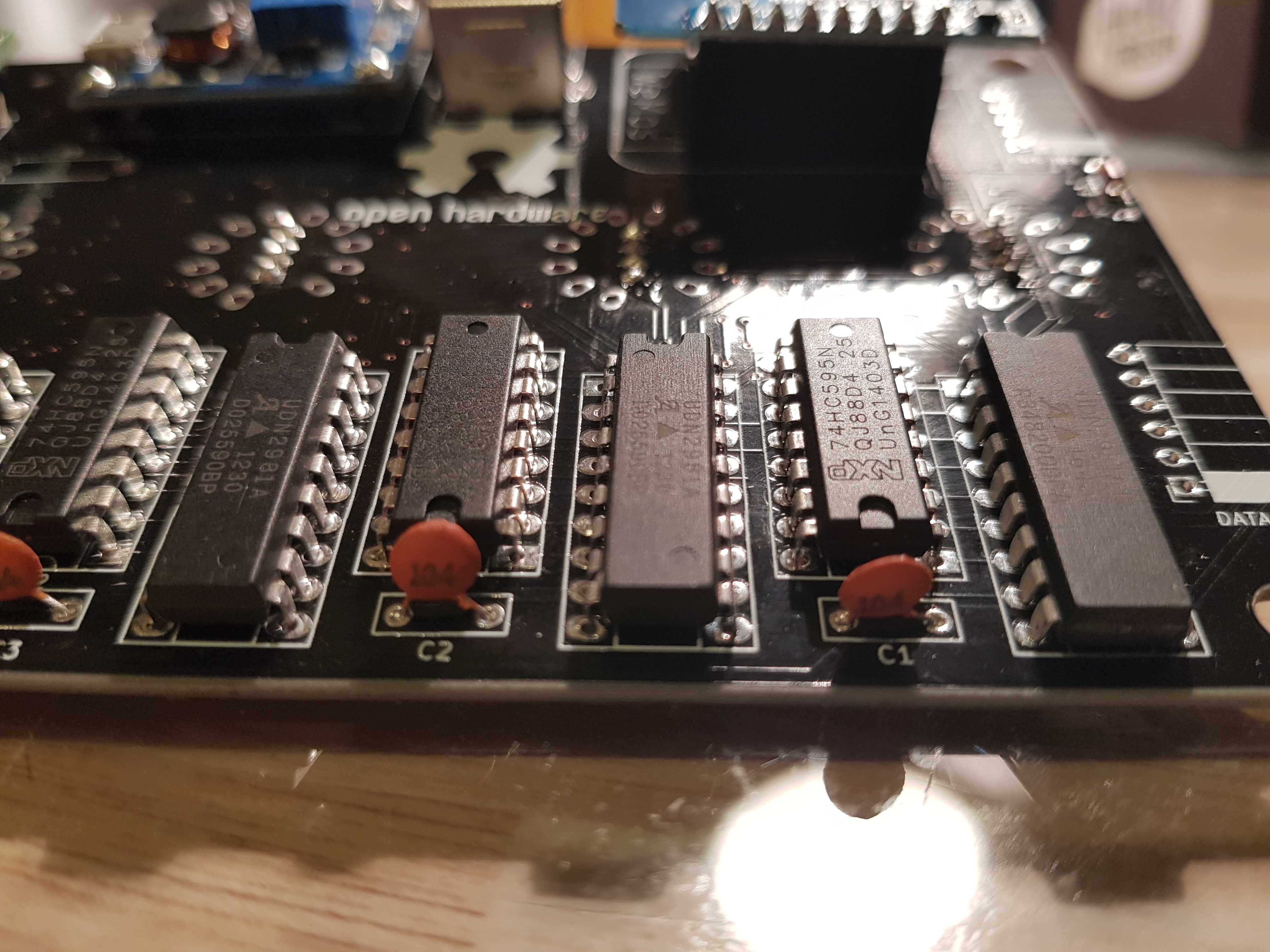
Install the shift register and VFD driver integrated circuits and decoupling capacitors
Insert each of the integrated circuits into their footprints on the lower side of the board. The 16 pin chips are the shift registers (74HC595) and the 18 pin chips are the VFD driver chips.
Note that they are inserted the right way round – there are small markings on the silkscreen which must align with the notches on the chip. The 16 pin chips have their notches facing AWAY from the USB socket, and the 18 pin chips notches face TOWARDS the USB socket. When soldering, it is a good idea to solder a few pins on each IC to anchor it into place, then move on, and come back to solder the remaining pins, to avoid overheating the ICs.
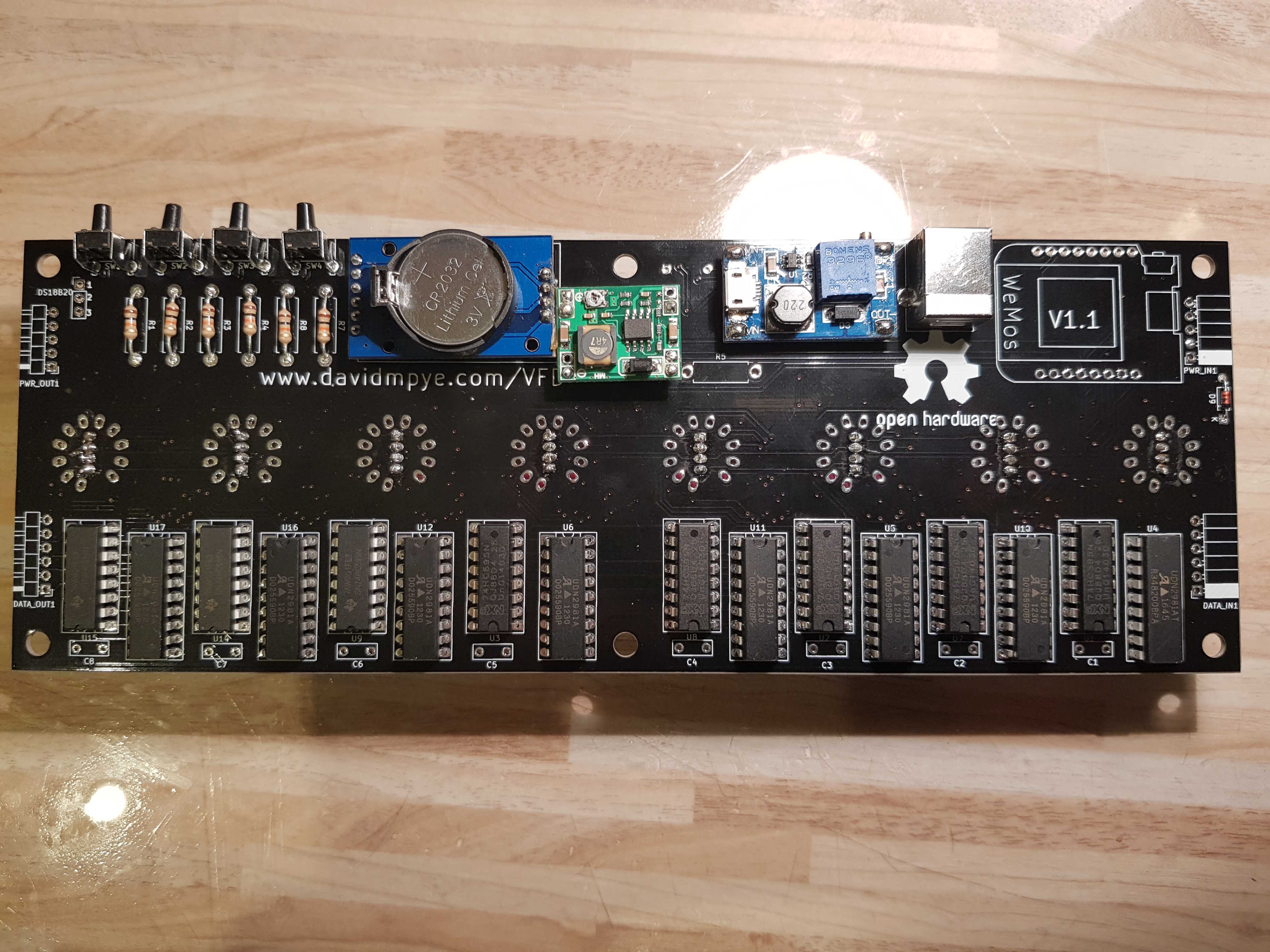
The decoupling capacitors can be installed either way round, and one sits adjacent to each of the shift registers:
Install the WeMos D1 and pin headers
In the WeMos packaging are a pair of pin socket strips (female) and solder these into place on the lower side of the PCB.
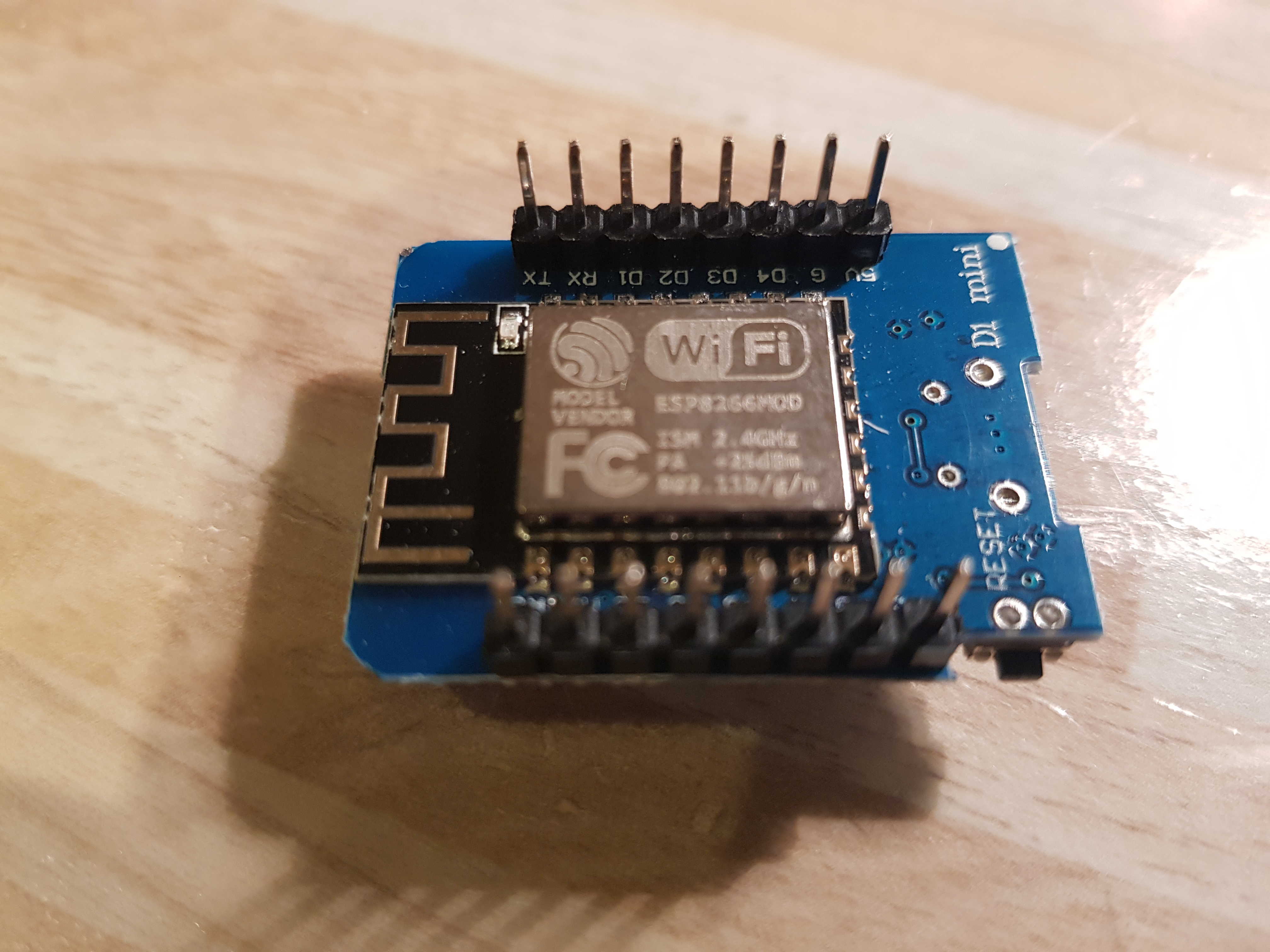
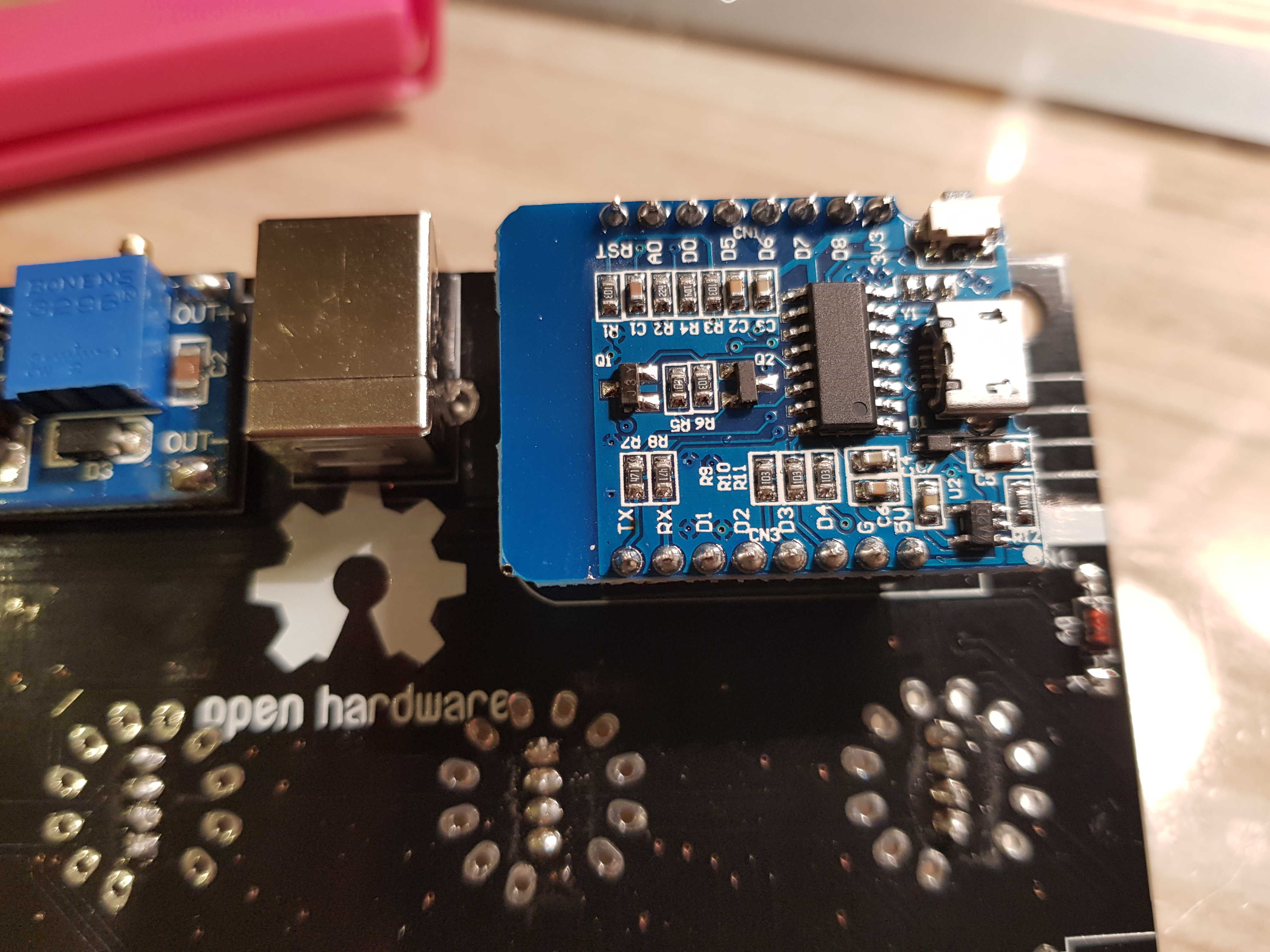
Solder the male pin header strips to the WeMos board as shown:
Then, push the Wemos onto its’ pin headers, so it sits like this:
Test of Wemos and LEDs
Apply 5V to the USB B socket again. You should now see the LEDs illuminate with a rainbow effect.
Install the VFD tubes
Errata
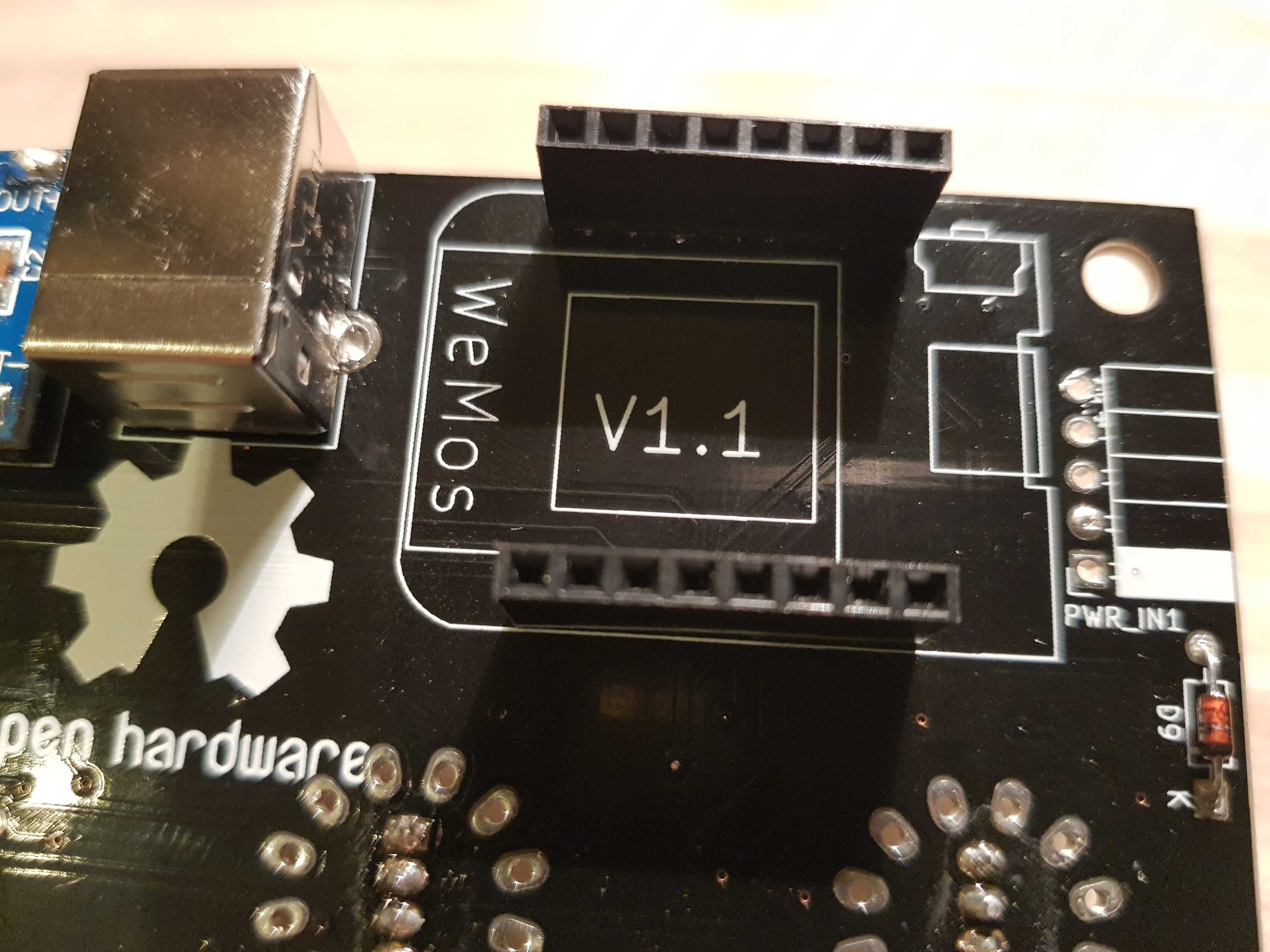
On PCBs marked V1.1 (version is printed under the WeMOS D1):
You need to use a small length of wire to connect the ground pins of switches 2, 3 and 4 to the ground pin of switch 1.
As shown below, use small lengths of insulated wire to connect the pins marked by red circles to each other.
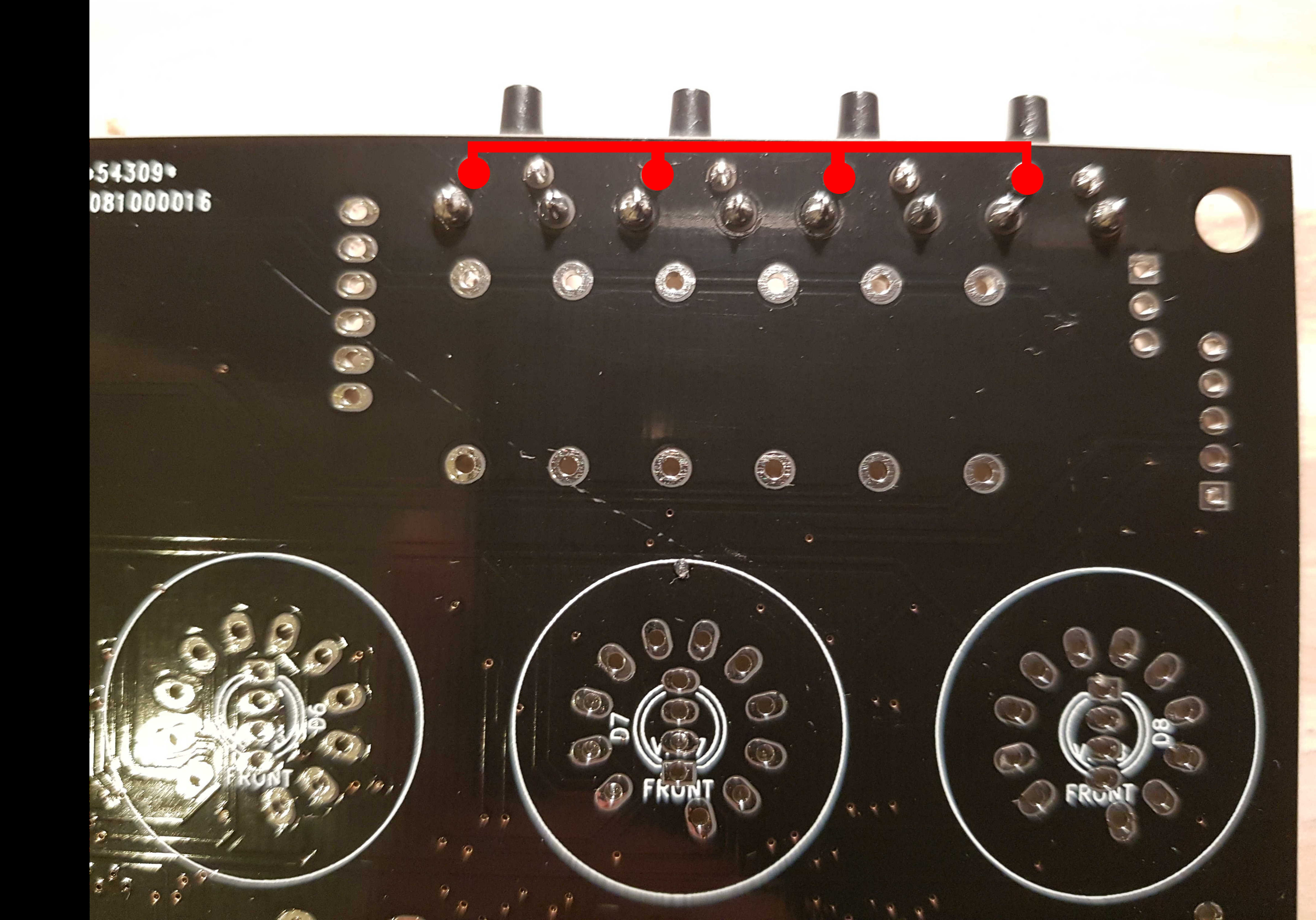
On V1.2+ boards, this is not required.