Introduction
Welcome to my website! I do a few things, personally and professionally. This is my personal website, and mainly contains things relating to my hobbies and interests, which include:
- Electronics and embedded software (firmware) development, often in Rust these days
- Amateur radio (licenced radio amateur, M0DMP)
- IoT/Smart home things, using Homeassistant
- Electronics repair
- Member of MakerSpace, a community Hackspace based in Newcastle/Gateshead
This website mainly contains:
- Some repair guides I've authored, giving useful info on repairing appliances etc (some of which the manufacturers don't want you to repair!)
- Archived PMR (Professional Mobile Radio) conversion information for now-obsolete radios (eg Storno/Tait/Dymar)
If you'd like to get hold of me, I use Gmail for personal emails, and my username is davidmpye.
I am also on Mastodon @DavidP
Repairs
Indesit IWDE126 IWDE126UK Drum bearing replacement
I have (had!) an Indesit IWDE126(UK) combined washer-dryer.
It’s about 7 years old and has had fairly heavy use. It’s started to develop a horrible rumbling noise when spinning, and I suspected the drum bearings might well be part of the problem.
On older washer dryers, the drum bearings could be replaced by removing the drum (and the outer plastic case, or tub) from the machine, undoing the bolts to split the drum, knock the old bearings out, drive in new ones, and rebolt the two halves of the tub back together (ideally with a new gasket to reduce the risk of leaks).
Unfortunately, like a lot of washer dryers now, the manufacturers have switched to sealed drums. The two plastic halves of the drum are welded together (either using solvent, or ultrasonically), so it is (supposedly) impossible to replace the bearings any more, leaving only the option of replacing the entire tub/drum unit. Unfortunately, including shipping etc, this is >£150 for my machine, making the repair pretty uneconomical even if I do the job myself.
After googling for a bit and finding a number of Youtube videos, some people have managed to replace the drum bearings on sealed drum machines by sawing the tub open along its’ weld lines, replacing the bearings and then drilling and bolting the two halves back together with a suitable sealant.
So, I did this, and it worked.
Here’s what I did (with some photos).
-
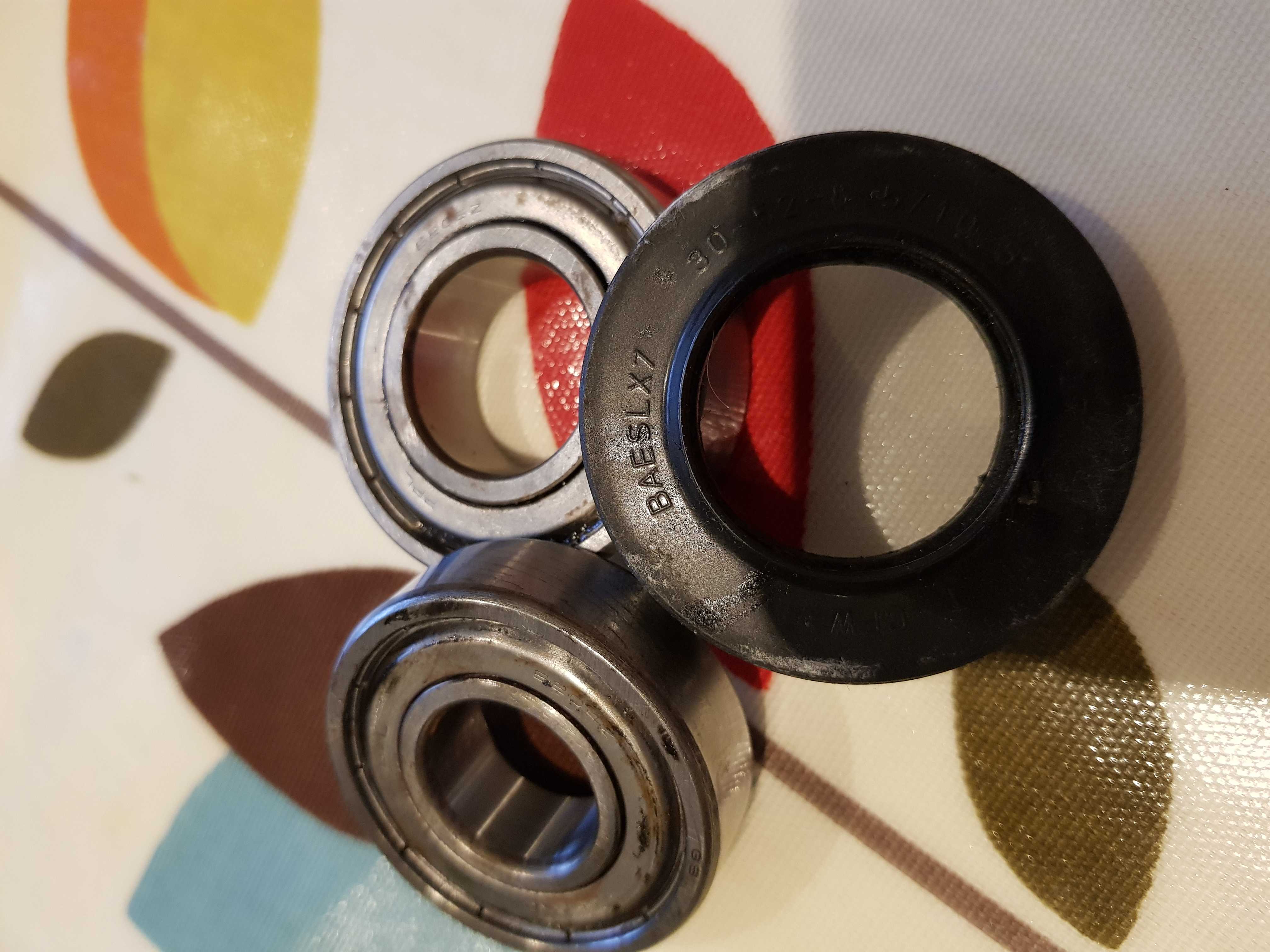
Find and order the bearings (and bearing seal) you need. For my machine, it turns out that you need a kit containing 6205Z and 6204Z bearings. Indesit supply a kit including the seal, as kit C00251855. It’s almost impossible to find anyone confirming what kit you need for the IWDE126UK, because Indesit don’t list a bearing kit, because the drum unit isn’t supposed to come apart! Old bearings and seal shown here:
-
Decide on a suitable sealant to use to re-waterproof the joint between the two halves of the drum. I used this sealant from RS. It’s described as “Bostik 91360 Bond-Flex 100HMA Black Silicone Sealant Non-Slump Paste 300 ml Cartridge” and in its’ key features, says “Forms a waterproof, flexible seal which provides a good level of movement accommodation

- Excellent adhesion to most building surfaces
- Suitable for internal and external applications
- For use over a wide temperature range; -60 to + 200°C”
So hopefully this will be durable enough – the temperature range is certainly fine.
-
Get nuts and bolts – I used M4 25mm allen-socket-head bolts, M4 locknuts and M4 washers (all in stainless steel) from my local nut and bolt suppliers. I probably used about 35 of them in total, spaced around the circumference of the tub. Remember tha tthe sealant won’t provide much mechanical strength, and the sealed tub has a large concrete weight hung off the front, so these bolts are all that is holding the tub together really…!
-
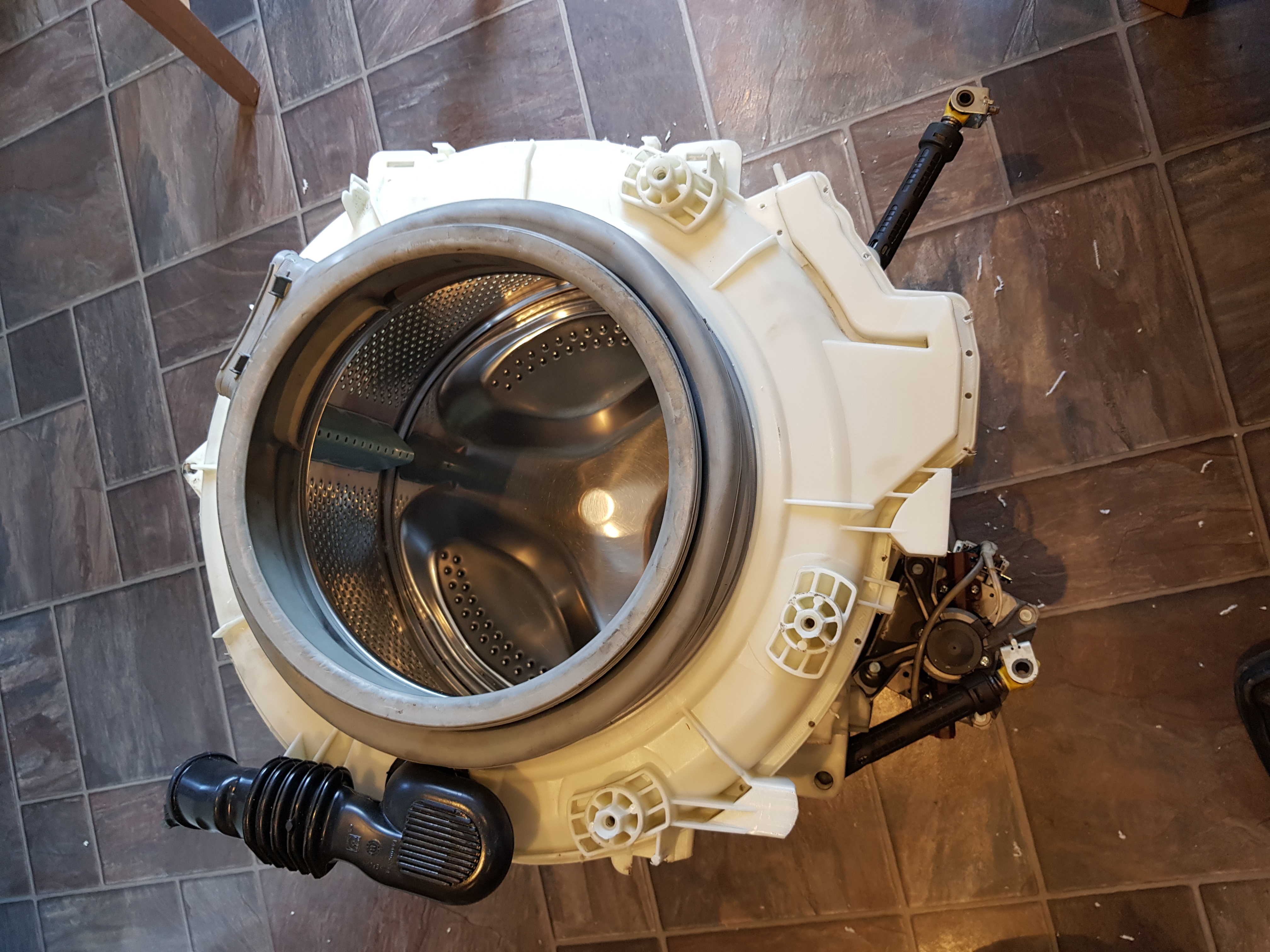
Drill the holes for the bolts before sawing the tub apart, as it’s easier to get the alignment right that way, then saw the tub and separate the two halves. I tried to drill the holes as cloes to the outside edge of the drum as possible to try to give enough surface area for the silicone to seal to in order to create a waterproof seal. Here’s a photo of the predrilled tub, then the tub with the front section removed:
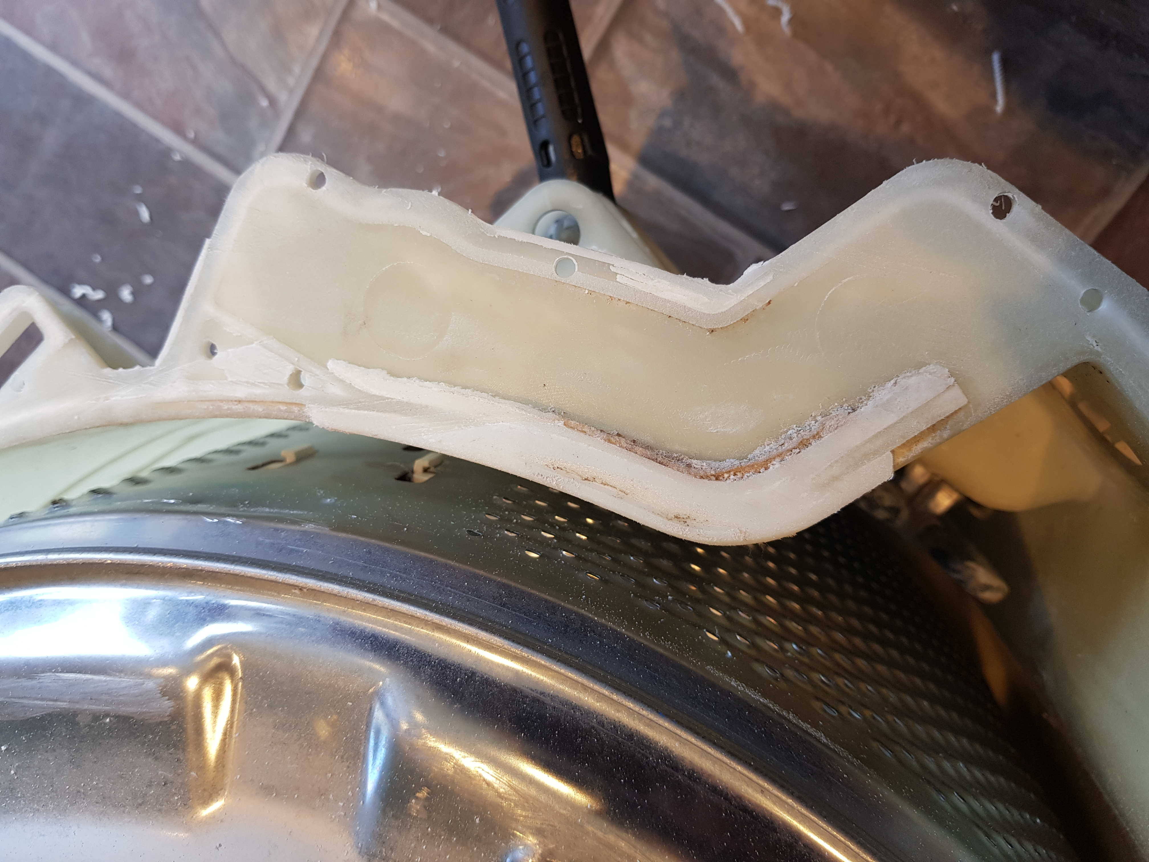
I used a few techniques to saw them apart – a dremel with a rotating disc to make a small slot at the top of the drum assembly (where it never fills up to!), then used a jigsaw with a short blade to carefully cut round most of the circumference, then a hand saw to do a few bits where the jigsaw couldn’t easily get to. You will have to saw through the snap-locks which originally held the drum together, though you can easily concentrate a few bolts round here, as it’s outside the bit that provides the waterproof seal. Note that there is an area at the bottom of the drum where the water pressure sensor connects to that is almost impossible to saw through perfectly because of its’ shape. I applied plenty of extra silicone here to get a good seal:
Once it was back together, I applied plenty of silicone to the outside of that bit too.
-
Replace the drum, knock out the bearings, and install the new ones, and the oil seal. Remember to only drive the new bearings home by hitting the OUTER ring to avoid damaging it. A pin punch or similar and a hammer would be ideal. Ensure both bearings are pushed fully home.
-
Apply a bead of sealant, join the two halves together, and bolt together. Allow >24hours for the sealant to dry.
-
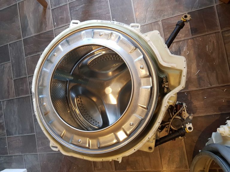
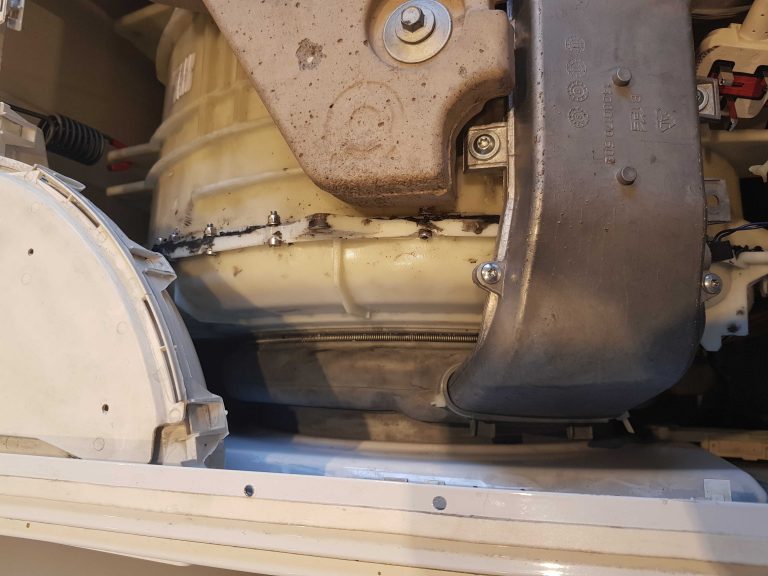
Reinstall and check it is watertight – good luck! Here’s a photo of the reassembled drum in place. (And yes, it’s watertight!)
Delonghi Perfecta machine fault – no steam!

I was given a machine from a work colleague to fix (a snazzy Delonghi Perfecta bean to cup machine) which wouldn’t froth milk or generate steam but did make coffee. When asked to steam, it just displayed “Heating Up…” then returned to the main screen.
I guessed the steam boiler element had probably failed open circuit, so opened the machine up, and checked its’ resistance with a multimeter (which was around ~50 Ohms), so that wasn’t the problem.
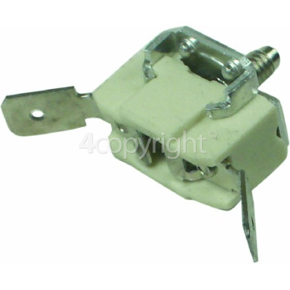
The boiler element is protected by a pair of thermal cutouts, which will permanently blow (open circuit) if the element overheats to prevent a fire. Both of these had failed. So I thought that buying a new pair of these would solve the problem.
Then I found this article detailing a similar fault, where the triac which controls whether the element is on or not fails closed circuit, meaning the element overheats and blows the thermal fuses. That article discussed the triac powering the main boiler rather than the steam boiler, but both are driven the same way.
This seemed to make sense and would explain why the thermal fuses had been blown.
Testing (carefully!) with the multimeter, I found that the element was continuously powered with full AC voltage even when the machine was on standby, so it became clear that the triac had failed closed circuit in this case.
So, to fix the machine, I replaced the two thermal cutouts from 4Delonghi: 2933924OH
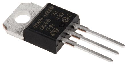
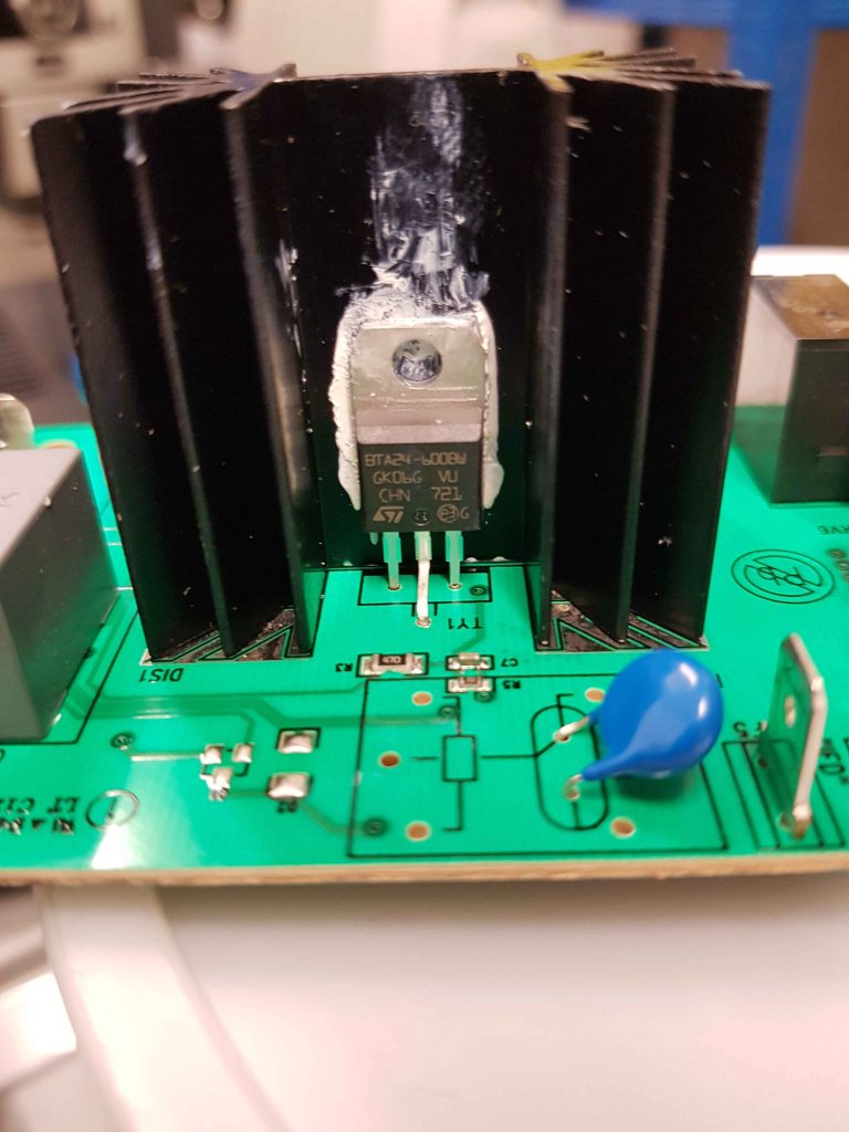
and the triac (from RS): Part No BTA24-600BW. From RS, it’s 6871029
and everything worked happily!
Here are a few photos of the repair:
-
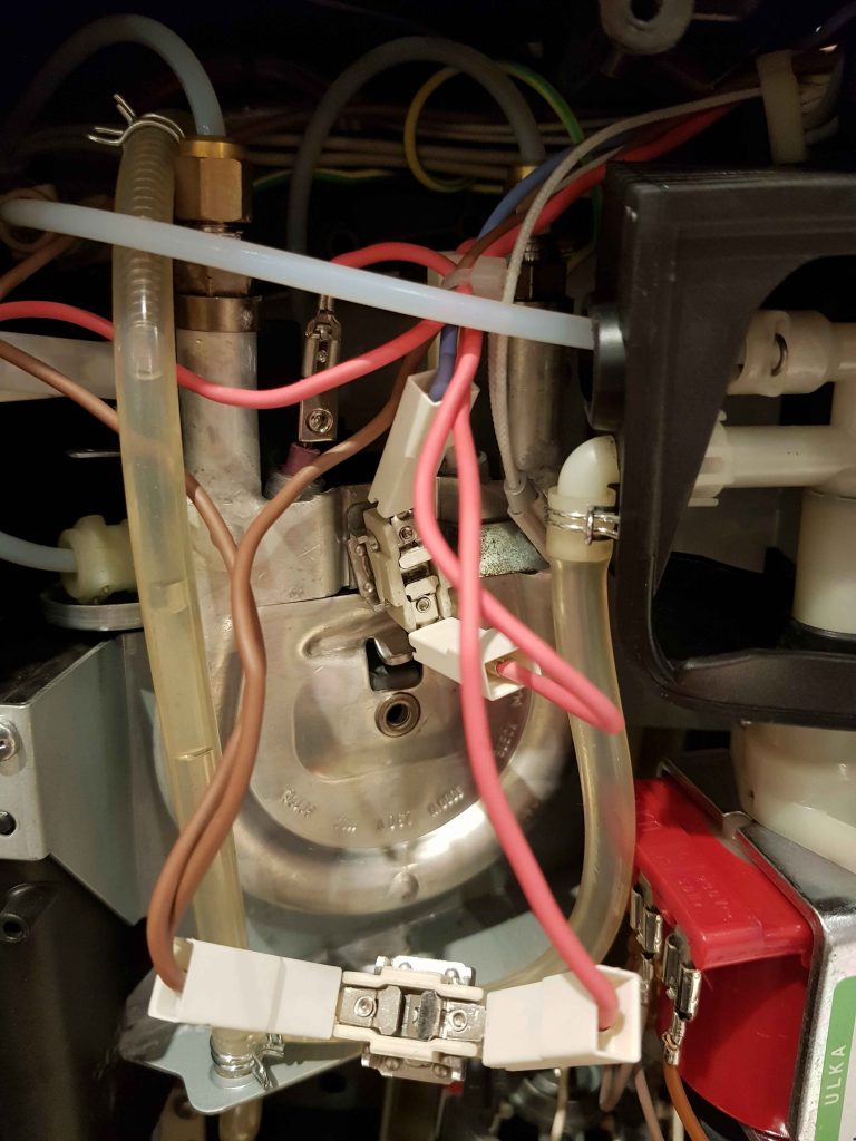
The horseshoe-shaped steam boiler (behind the back cover of the machine). You can see one dangling thermal fuse which I’d unbolted, the other at the centre of the image, and the two terminals of the boiler element. Both fuses are wired in series with the element – one in series with the triac-switched feed from the control board – lilac wire, and the other in series with the neutral return (brown wires).
-
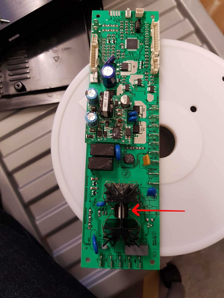
The control board, with the failed triac indicated with an arrow. The one on the other side of the heatsink controls the boiler for the hot water. (and can fail in a similar way!)
-
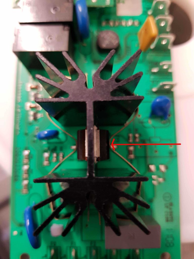
Faulty triac closeup (arrowed)
-
The resoldered and re heatsink-compounded triac on the main circuit board prior to reinstalling the retaining clip and reassembling the machine.
PMR radio section
Introduction
Many of the things here are probably largely outdated now - either the radios themselves have long since ended up in landfill, or been superseded by £50 Chinese-made handhelds which far exceed their capabilities (if not RF performance...!)
Storno 5000 Series
These guides relate to the Storno 5000 series - CQM5110 and CQM5660.
Most of these radios are long since in landfill (including the ones I'd played with years ago). However, I've kept this archive information around for the last 20 years, so I might as well not delete it now....
The guides are accessible from the site index.
Useful files
- GWM Radio's Storno conversion guide (VHF)
- Ham Radio Today's conversion guide (UHF)
- CQM 5110 Service Manual (VHF)
- CQM 5660 Service Manual (UHF)
Dismantling the Storno 5000 series
Removing the top and bottom casings
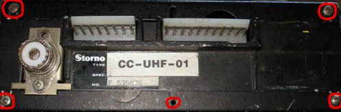
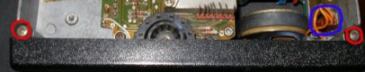
Firstly, remove the top and bottom covers from the radio by removing the screws circled in red, and lifting the covers up, then sliding them back slighly to remove them.
Removing the front panel
Remove the two screws on the top (circled in red), turn the radio over and remove the two corresponding screws on the underside. Unclip the front panel speaker connector (if present) and pull the front panel horizontally off the radio.
Removing the synthesizer board
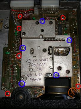
Remove the screws circled in blue, and lift off the die-cast housing. Remove the red-circled screws, and lift the board gently (from both the back and front – remove the front panel first). There are long pins which protrude the board to communicate with the RF board underneath – avoid bending these when removing the board.
Removing the RX/TX board
First, remove the screws circled in blue, and lift off the die cast housing. Then, remove the red-circled screws.
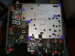
In the top corner of the radio (PA section), remove the red-circled screw, and then the four blue-circled screws which anchor the PA transistors to the radio chassis. These screws fix into captive nuts underneath the synth board on the other side of the chassis. Sometimes these nuts fall out when the screws are withdrawn – if this happens, you will need to remove the synth board to resite them. I’d recommend applying a blob of silicon sealant to the nuts to ensure they are held captive in future if you encounter this problem.
Loosen the screw nearest the top side of the radio on the SO-239 socket – it does not need to be removed completely. Then, lifting from the front of the board, and the SO-239 at the back, lift the RF board free of the radio chassis.
Reassembly is accomplished by reversing the above steps – It is worth applying new thermal conductive paste (you can often get these from computer shops) on the bottoms of the PA transistors on refitting to ensure good conduction of heat to the radio chassis.
Introduction
Converting the Storno CQM5112 to the 2m band is reasonably easy, though it does require a bit of patience, and a few tools etc. A few capacitors on the RF front end need replacing to improve sensitivity, and two new crystals from Quartslab are needed to configure the synthesizer for 144MHz. The modification steps outlined here are based on the original document GWM radio supplied with the radios, although I have simplified some steps I did not find to be necessary.
Parts needed
Crystals:
- 1x 43.36666MHz series resonant crystal (available from Quartslab)
- 1x 46.93333MHz series resonant crystal (available from Quartslab)
Capacitors:
- 1x 8.2pF ceramic plate
- 1x 10pF ceramic plate
- 2x 12pF ceramic plate
- 1x 15pF ceramic plate
Tools needed
- Screwdrivers
- Plastic tipped ‘twiddlers’ for the ferrite cores – do NOT use a small screwdriver, it will crack the cores.
- Dummy load
- VHF power meter reading 20-50Watts
- Frequency counter (not ESSENTIAL, but recommended)
Steps
Component changes
-
Remove the RF board from the radio (follow the instructions here: Storno 5000 dismantling)
-
Remove the screening cans circled in red by desoldering their mounting pins from the underside of the board.
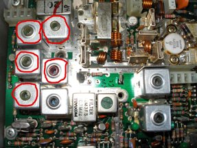
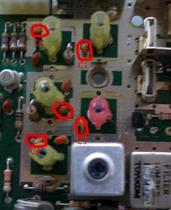
- Remove the capacitors circled in red and replace them with the following values:
- C1: 12pF
- C2: 10pF
- C3: 12pF
- C4: 15pF
- C5: 8.2pF
- Once this is done, replace the screening cans and resolder them into place. Remount the board in the radio. (If you want to fit the bicoloured LED modification, this is an ideal time to do it – Storno 5000 bicolour LED for more details)
Synth alignment
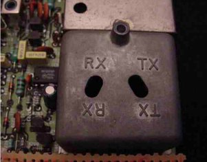
- Remove the old crystals from the crystal holders labelled TX and RX in the photo and fit the new ones. (TX: 46.93333MHz, RX: 43.36666MHz). If you find it difficult to remove the old ones, it may be easier to remove the synthesizer die cast housing first.
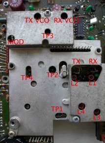
-
Connect a diode probe to TP1, and adjust L1 and L3 for maximum deflection on RX. Operate the microphone TX switch (the TX led will NOT illuminate yet) and adjust L2 and L4 for maximum deflection. Next, connect a high impedance DC meter to TP3. Adjust the RX VCO trimmer to obtain approximately 2v deflection.
-
Operate the microphone TX switch and adjust the TX VCO trimmer to obtain approximately 2v deflection. At this point, the red TX led should now illuminate when the TX switch is depressed. If you have an oscilloscope available, connect it to TP2 and adjust L3 and L4 for maximum amplitude. Connect a frequency counter to TP4. Adjust L1 to obtain a frequency of 133.300 on RX, and L2 to obtain 144.000 on TX.
RF board layout:
Receiver alignment
-
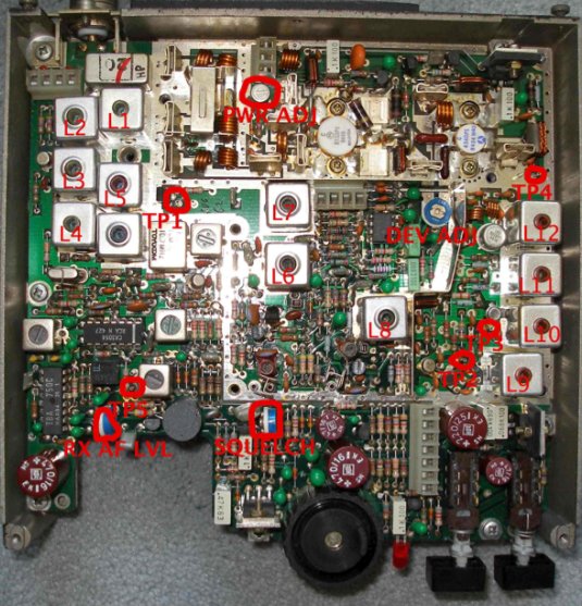
Connect the diode probe to TP1 as shown below and adjust L6 and L7 for maximum deflection. Then, either connect a signal generator to the SO-239 socket and apply a signal of 144.000MHz. Alternatively, connect an aerial and provide a strong local signal.
-
Connect the diode probe to TP5 and adjust L1, L2 to peak the reading on the meter. Detune L3 and L5 as much as possible. Then, adjust L4 to peak the reading as much as possible. Do not adjust L4 again after this point. Adjust L3 and L5 now to peak the reading on the meter. Now, L1 and L2 can be readjusted to maximise the reading. Keep reducing the RF input each time and readjust L1, L2, L3 and L5 to maximise the reading. Finally, adjust the squelch potentiometer to set the squelch to the desired level.
Transmitter alignment
-
Connect a power meter and dummy load to the aerial socket. Key the radio into TX and leave it transmitting while the next steps are followed.
-
Connect a DC voltmeter to TP2 and adjust L8 to obtain the maximum reading. Then, connect the meter to TP3, and adjust L9 and L10 for maximum. Connect the diode probe to TP4 and adjust L11 and L12 for maximum.
-
At this point, the power meter should indicate power is being output. I recommend at this point carefully readjusting L8, 9, 10 and 11 to peak the power output. Once this has been done, check the transmitted signal with another receiver to check it is stable (no whistling etc).
-
Finally, adjust the power output to a level not exceeding 25W using PWR ADJ as labelled in the diagram.
-
Deviation can be adjusted if necessary using the deviation control on the RF board marked DEV ADJ – the control labelled MOD on the synthesiser board is not a deviation control as such and should ideally be left alone. If you find that you cannot obtain sufficient deviation from the RF board control, it can be carefully adjusted however.
Storno 5000 100-channel EEPROM conversion
Introduction
The Storno 5000 is in my opinion ideal for a 100 channel conversion.
Firstly, as the prom board needs to be replaced anyway, it’s well worth the extra effort to build a 100-channel solution, rather than a 10-channel diode matrix solution, for example.
Secondly, there’s plenty of space in the top half of the radio chassis, which makes installing a veroboard-based solution easy.
The mod outlined here gives you 100 channels, with simplex, -600kHz repeater shift, and reverse repeater shift, depending on the position of the front panel switch.
Files needed
Click to download:
EEPROM image file (S3F format)
Details
First, convert the radio to 2m following the instructions on the 2m conversion page.
Remove the selcall board in the left hand side of the ‘top half’ of the radio. If you want to install a 1750Hz toneburst later, remove the push-switch that used to fit through the front panel from the selcall board.
Remove the prom board, and desolder the 14-pin connector from it, as you will need it later on.
I built my circuit on veroboard, and also fitted in a 1750Hz toneburst circuit, and still had plenty of space remaining. The circuit diagram for the 100 channel mod is as follows (thumbswitch and data conns omitted for clarity)
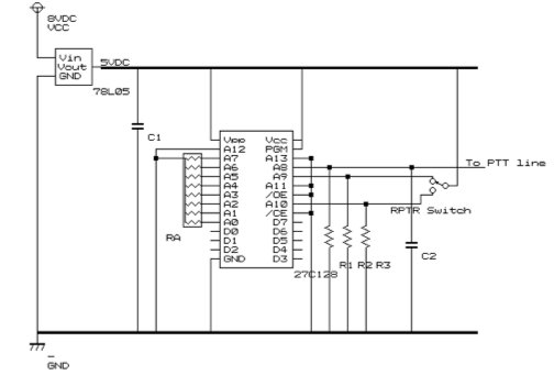
Notes:
- Address lines A0->A7 are used for the thumbswitches
- Address line A8 is used for PTT (low on TX)
- Address lines A9 and A10 are used for repeater shift and rev repeater shift respectively.
- A11, A12 and A13 are grounded (no pulldown resistors needed) – not used.
Parts:
- C1, C2: 10microFarad tantalum-bead capacitors
- RA: 10K ohm resistor pack
- R1, R2, R3: 10K ohm resistors
- EPROM: 27C128
- Voltage regulator: 78L05 5V output regulator
- Repeater shift switch: 3 position, centre off, latching switch
- Thumbswitches: 2x miniature 0-9 thumbswitches.
- 14 pin connector for synth (salvage this from the old PROM board)
Connections
-
Synth connector: 8V DC input is found on pin 1 of the connector.
-
D0 of EPROM -> pin 2 of the connector
-
D1 of EPROM -> pin 3 of the connector
-
D2 of EPROM -> pin 4 of the connector
-
D3 of EPROM -> pin 5 of the connector
-
D4 of EPROM -> pin 6 of the connector
-
D5 of EPROM -> pin 7 of the connector
-
D6 of EPROM -> pin 8 of the connector
-
D7 of EPROM -> pin 9 of the connector
-
(Pins 10->13 are unused)
-
The PTT line is found on pin 14 of the connector.
I numbered the pins as follows:
- Thumbswitches:
Connect the ‘common’ pole of both thumbswitches to the 5VDC output of the voltage regulator. ‘tens’ switch: 8 -> A7 of EPROM 4 -> A6 of EPROM 2 -> A5 of EPROM 1 -> A4 of EPROM
‘units’ switch: 8 -> A3 of EPROM 4 -> A2 of EPROM 2 -> A1 of EPROM 1 -> A0 of EPROM
EPROM: The EPROM image designed to work with the above schematic is available for download above.
A similar conversion will work for UHF Storno models also, but will require different EPROM images to be made.
It would be possible to have 255 channels by using hexadecimal thumbswitches and a different EPROM image, but I decided not to as I think in decimal and 100 channels gives me a pretty reasonable coverage of the band.
Fitting it all together
Find a piece of veroboard large enough to fit inside the radio, replacing where the toneboard previously sat. This means you can use the original two screws for mounting it into the radio. If you choose to use a smaller piece, you will have to find an alternative method of securing it into the radio.
Assemble the circuit using the details above. If you want to use the 1750Hz toneburst modification also, make sure you leave enough space on your piece of veroboard to allow you to mount the switch (earlier removed from the selcall board) to allow it to protrude through the front panel in the correct place.
There is sufficient space between the veroboard and the radio chassis to use a socket on the EPROM, if you so desire. I did on my modifications, so that I can replace the EPROMS easily if needed in future.
Power from the circuit comes from two points:
12VDC from Pin 14 of the synth connector GND from the chassis of the radio – I soldered a piece of braid to the bottom of the veroboard where the rear mounting screw affixes to the chassis, providing a robust ground connection. This then powers all the circuits on the board.
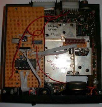
A photo of the board fitting into my storno is shown below.
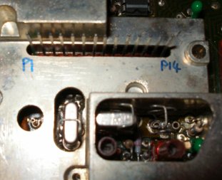
Connections to the synthesizer pins: I used a small piece of veroboard, the original 14 pin connector from the PROM board, and a length of old hard disk ribbon cable to connect it to the main veroboard. A closeup of this arrangement is shown here:

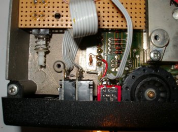
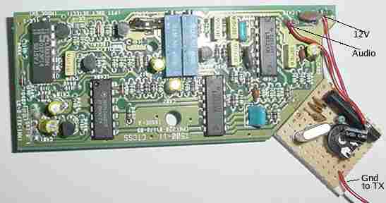
I used more ribbon cable to connect the thumbswitches and the repeater switch cable to the main prom board, as the photo below shows. To the left of the photo below, you can see the toneburst switch mounted to the prom board ‘upside down’ through the tracks. This photo shows also that I had to remove a small corner of the upper synth circuit board in order to fit the thumbswitches. This contained only a single track, which the red wire shown above bridges. You may not need to do this, depending on the size of your thumbswitches.
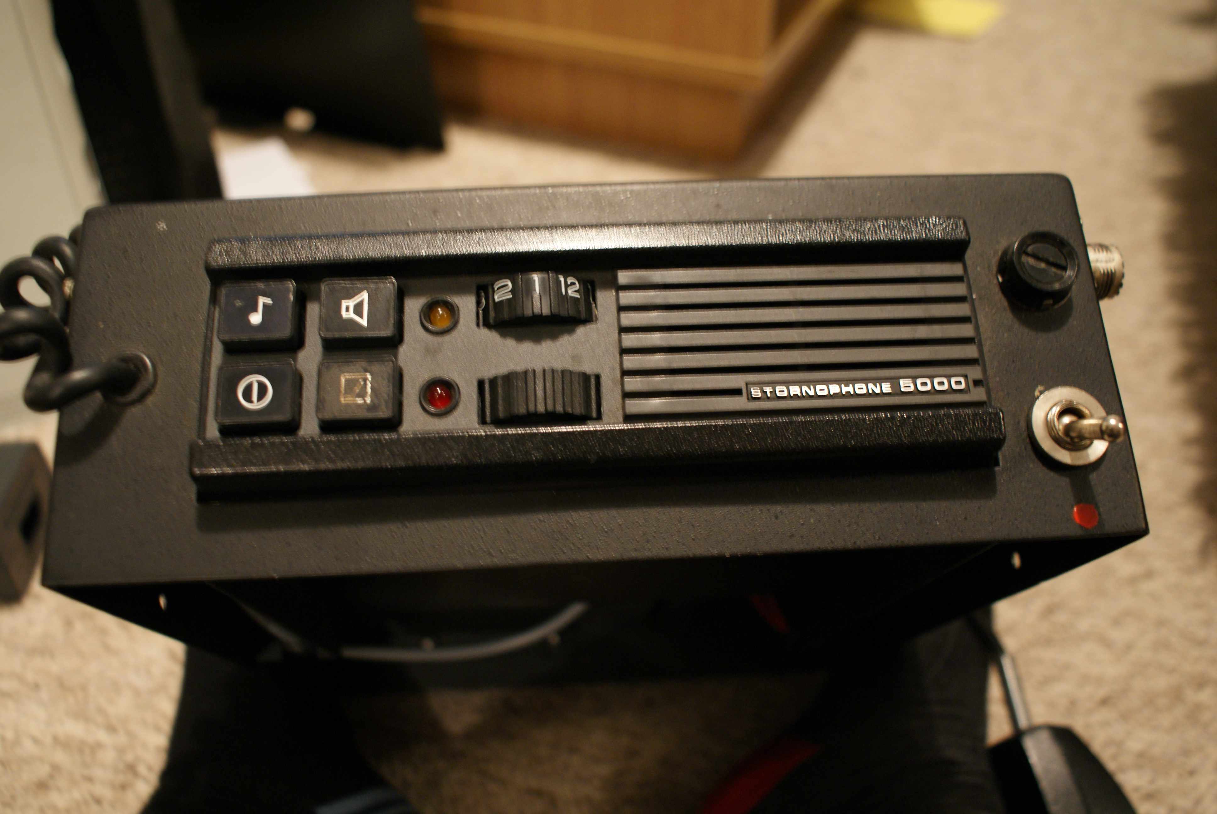
To provide some ideas about how to mount things to the front panel, here is a photo of the front of my modified Storno:
I chose to fit the repeater/simplex/rev repeater shift switch through the now unused hole at the top, previously used for the LED on the selcall board. The thumbswitches are fitted into the hole left by another selcall board button (a small amount of filing might be required depending on the size of your thumbswitches. The tone-send button on the selcall board has been reused for the 1750Hz toneburst modification. The original 12 position rotary switch is still present but serves no function. I might replace it with a small S-meter or similar eventually.
1750Hz toneburst
Introduction
This modification is best combined with the 100-channel modification, as there’s plenty of room left on the 100-channel veroboard to fit this in, and it can share the power and ground connections. It also provides a convenient location to mount a push switch so that it protrudes through the front panel. The modification fitted into my radio uses one of the switches from the selcall board to activate the tone generator and to key the radio into TX when the button is pressed.
Circuit
I used a design by Andy Potts, the layout of which is reproduced below, with his permission. His website is available here.
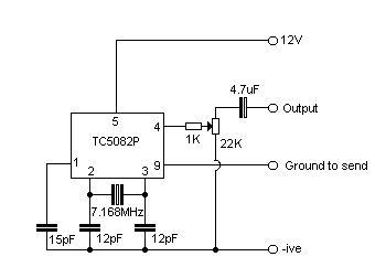
This design does not have any provision for frequency adjustment – this is because the frequency is crystal controlled, and is extremely accurate (even accurate enough to open my ‘home’ repeater, GB3SR, which is notoriously picky about such things!)
Connections
The +ve connection comes from pin 14 on the synth connector (the one on the far right, with the radio front facing towards you) -it’s 8VDC. I’ve numbered the pins as follows:

GND comes from the chassis of the radio – the veroboard design I used has a piece of braid soldered to the bottom of one of the mounting screws for this. The ground-to-send line is wired up using one gang of the dual gang front panel switch that I salvaged from the selcall board. Connect the common (centre two pins) to ground, and connect one of the rear gangs to pin 9 on the TC5082P of the toneburst circuit. The other gang is wired to the PTT line of the microphone socket on the back of the radio, so that pressing the toneburst switch keys the radio into TX as well as enabling the tone generator. The audio output from the circuit is fed into the audio connection on the microphone socket on the back of the radio. The deviation of the tone can be adjusted using the potentiometer in the circuit above to set the deviation at a suitable level. The connections to the microphone socket are shown here – looking from the front of the radio.
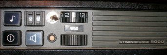
The connection on the left (2nd pin in from the left) is the PTT line and is wired to the TB switch. The connection on the right (4th pin in from the left) is the audio output from the toneburst circuit. To give you an idea of the front panel layout I used, this is shown below – the toneburst switch is on the top left.
Storno ‘portable case’ curiosity
At a local radio club bring and buy sale, I came across one of these:
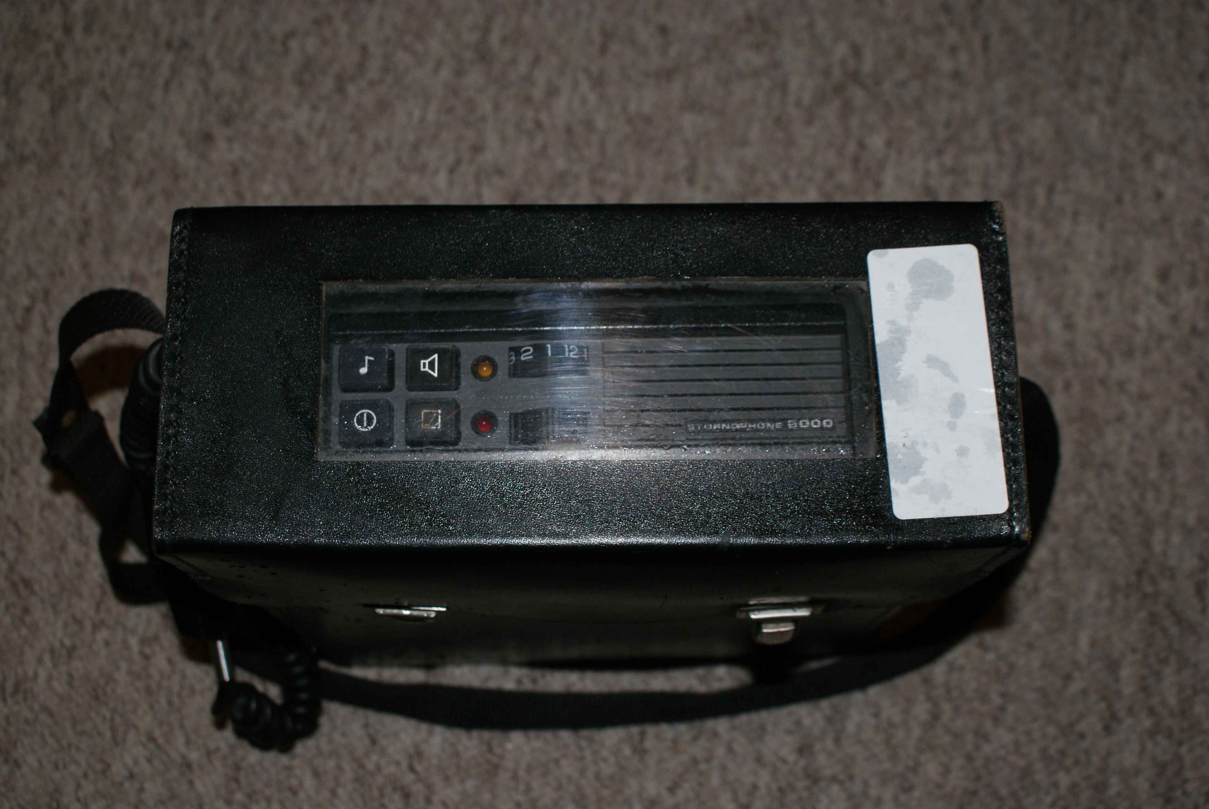
It’s a portable carrying case for a Storno 5000 series radio along with a leather outer case. It has a clip-on lid with a clear plastic viewing window so you can see the top of the radio with the lid shut. It is certainly splashproof but wouldn’t say much more than that about it!
It had an old 4m crystal controlled storno in, so I have removed that and will put one of my synthesized ones in instead.
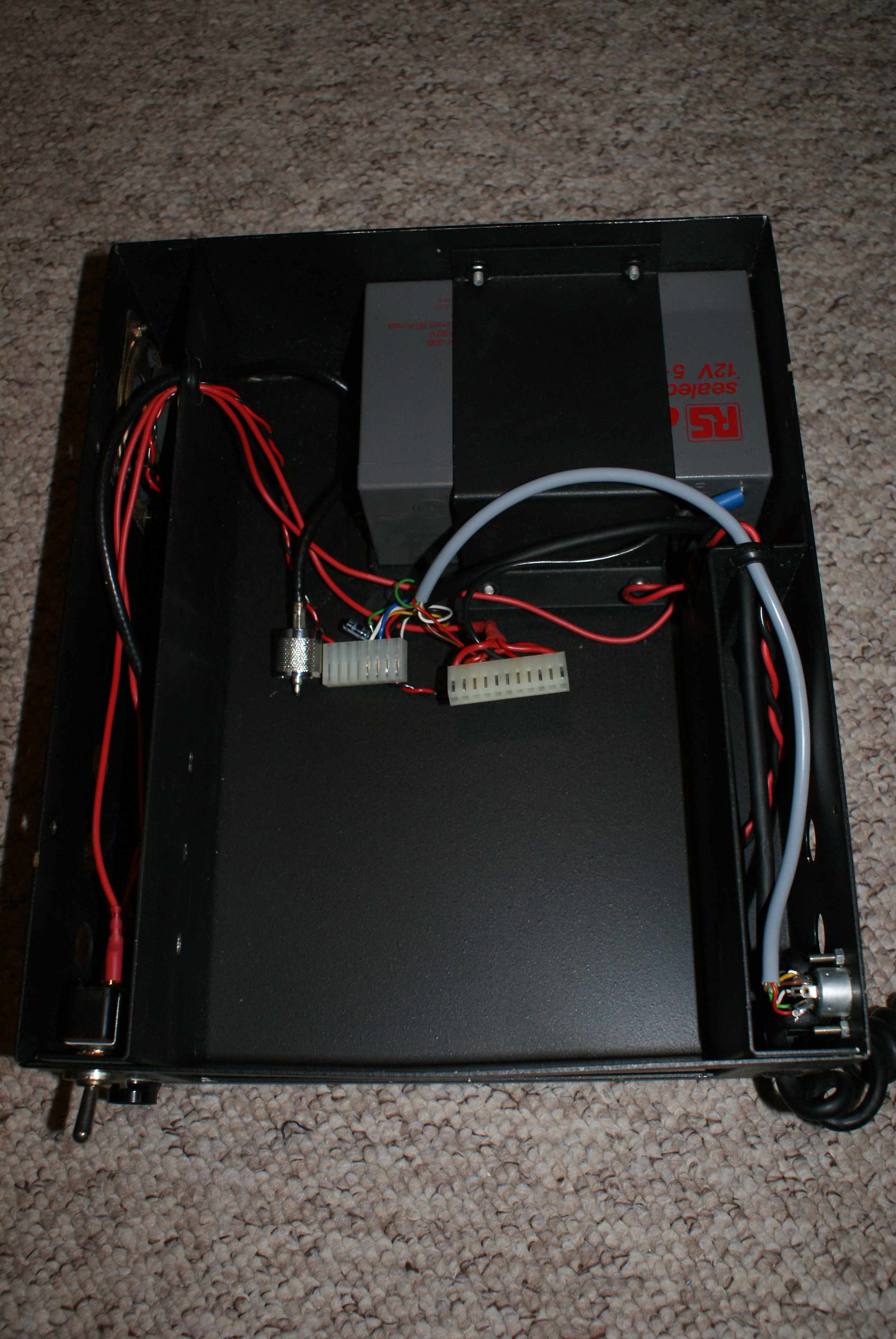
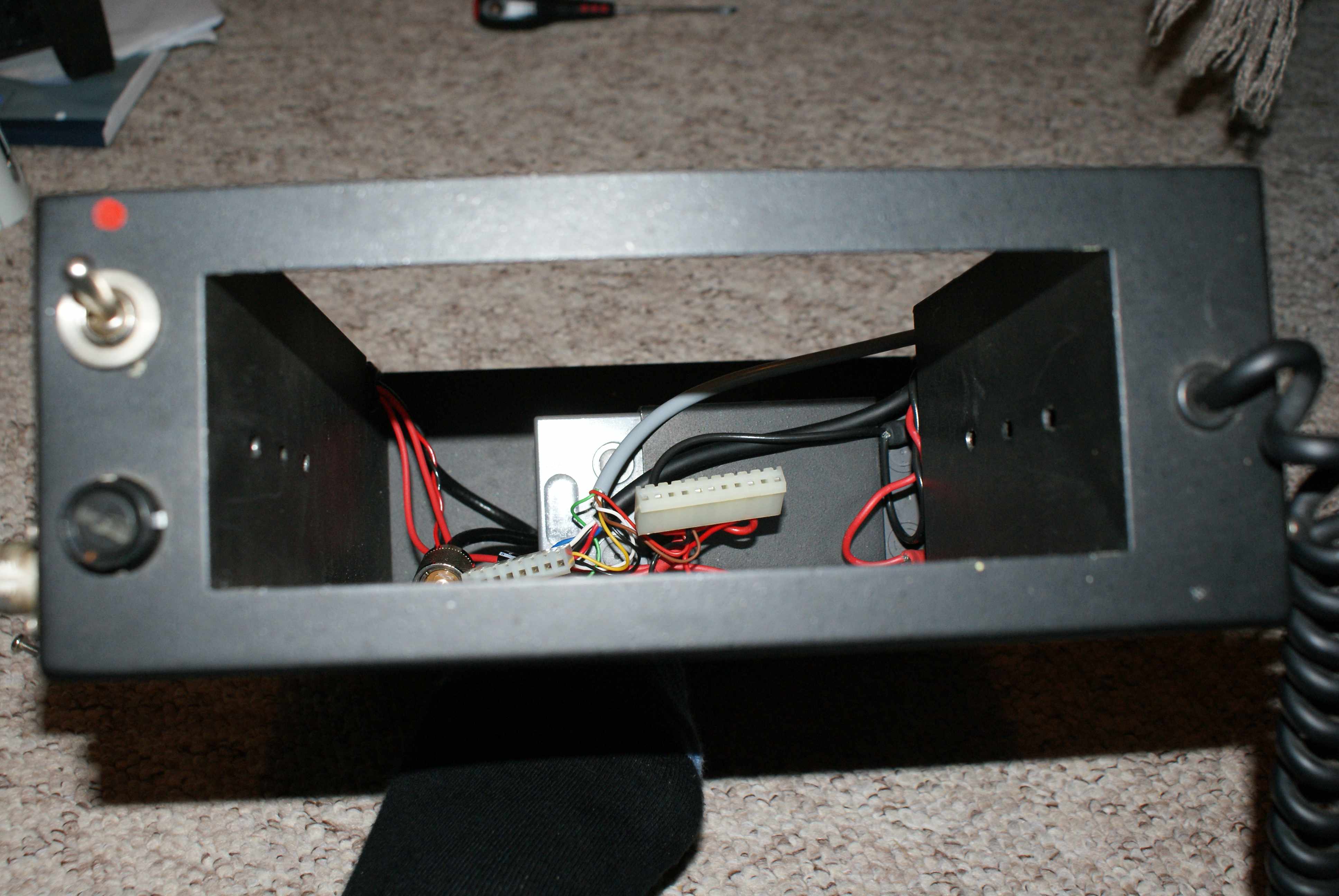
It has a sealed lead acid battery in the lower part of the case, an external power on/off switch and fuse, a loudspeaker (behind a small grille of drilled holes) and an external SO-239 connector for the antenna.
It also has a pair of DIN connectors on the side (a 2 pin one for charging the lead-acid + powering the set, and an 8 pin one, which I am guessing allows another external mic/speaker, but I haven’t looked at these yet!
Not sure that it is portable enough to take on a hike unless you wanted to prove a point, but it would be a good portable ‘base station’ for field work perhaps!
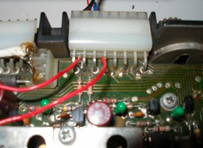
A few more pics of the ‘guts’:
Tait T500 Series
The Tait T500 series radios are a ‘compact’ mobile radio series, available in a number of configurations. Some are useful for 4m/6m, some 2m band candidates (T530/535), and some are 70cms capable (T555?). There are also a number of other versions, some of which are trunked, and some which are 200MHz targeted – which are unable to cover 2m/70cms – avoid these! The radios themselves are constructed from a two plastic ‘lids, which is coated with conductive paint on the inside for shielding purposes. Along with the radio PCB these form the chassis and give the radio its rigidity. They are fitted with BNC connectors for antenna circuits, and have hardwired microphones, which are connected at the front of the radio, entering the set just under the front panel.
Most are two channel, although Tait do sell a 99-channel conversion module, which allows frequencies to be programmed into the radios using EPROMS. My 100-channel conversion design uses a similar principle.
Advantages
-
No crystals involved – fully synthesised. Stornos, although synthesised, require a pair of new crystals and can only tune within 2MHz (approx) of this, whereas the Taits are tunable over a large frequency area.
-
No component changes necessary – NONE. Not even capacitors in the receive coils, as these radios are spec’ed for use in a frequency range which covers the amateur bands.
-
Aesthetically pleasing – sort of! Most of the major controls – vol, squelch, call (toneburst) are already fitted to the front panel. All that is needed to give a 100-channel set is to cut a small opening for thumbswitches.
-
Compact – These radios are considerably smaller and lighter than Stornos, or other PMR models popular conversion radios. Unfortunately this is both a blessing and a curse – it can make fitting additional boards etc, quite awkward.
-
Very stable – for example, it is hard to tune up the transmitter in such a manner that it is unstable. This is the opposite of such radios as the Burndept Dymar, which by comparison, is very hard to tune stably!
-
Clearly marked – The circuit board/s of the Tait are extremely well silk printed, and service adjustment points, such as the Deviation Adjust Potentiometer is well marked. This avoids the need to pore over a layout diagram to find those elusive components!
-
Lots of documentation – Tait have just released all the service manuals and other documents, which are very helpful for info about how to tune up the radios etc.. See here
Disadvantages
-
Can be hard to find these days – not really a fault of the model itself!
-
Vehicle mounting kits are very rare – the mounting kit consists of a metal tray and two clips which attach to the sides of the radio, and it then slides into the tray. A special key is required in order to remove the radio from the case.
-
They get hot – As much of the radio is plastic, apart from the transmitter heatsink area, the radio can become very hot if used for long periods on transmit. This is simply a design ‘feature’ – and usually doesn’t cause damage unless excessive. If you are using them for a high duty-cycle application, simply reduce the power output.
Useful files
I’ve collected a few files from Tait over the years, that might be useful to a few people.
Here they are:
T535 VHF -> 2m Conversion
Introduction
The Tait T500-series radios are very easy to convert to 2m operation, as they were designed for wideband usage, and therefore no component modifications are required to convert them to 2m.
However, there is some retuning required, and this will require some patience and some basic test equipment. I recommend at least the following:
- A multimeter, either digital or analogue
- An RF Power meter (a cheap-ish VHF Power/SWR meter is adequate for this).
- A frequency counter (you can manage without this in a pinch, but it does make life much easier!)
- A set of plastic tipped trim tools – do not use screwdrivers under any circumstances
- A dummy load – for social reasons!
The frequencies for this set (both transmit and receive) are set by the diode matrix situated on the right hand corner of the radio behind the front panel.
This needs to be modified initially to a 2m frequency to allow the radio to be tuned, even if you later intend to do the 100 channel modification described elsewhere on this site
Before beginning this procedure, remove the CTCSS board (if fitted).
You simply need to remove it – on these radios it is not necessary to bridge out any links if it is not present.
Step 1 – Set up the diode matrix
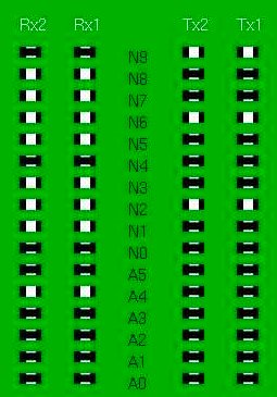
Initially, the best place to set the diode matrix is on 145.000 MHz as it is in the middle of the desired band. This is therefore a good place to tune for maximum performance (ie max power out on Tx and max sensitivity on Rx).The diode matrix has four columns on it – RX2, RX1, TX2, TX1 – we only need to change a matching pair – I suggest RX1 and TX1 (the transmit and receive frequencies for channel 1.
Although we are making a simplex channel, the values for RX1 and TX1 are different due to the IF of the receiver. The following picture shows the diode matrix calculated for 145.000MHz. You only need to copy RX1 and TX1 as in this example both channels are set to 145.000MHz simplex.
Step 2 – Getting the VCOs to lock
The next step is to adjust the VCO trimmers to bring the VCOs into lock for both Tx and Rx. Once this step is complete, you will be able to receive (assuming you have disabled the CTCSS on Rx – you can do this by removing the tone board temporarily during testing) – but don’t expect ANY sensitivity whatsoever). You will also be able to Tx (again, don’t expect ANY measurable power output though! Set the radio to channel 1 (assuming you set channel 1 on the diode matrix board to 145.000). Locate the VCO housing and the test point – the VCO housing is a small die cast housing on the right hand side of the radio, with two holes labelled TX and RX. Just beneath this is a set of three jumper-type pins sticking up from the board (labelled TP-2). The middle pin is the VCO lock test point – connect a multimeter to this and set to a range suitable for measuring 4 Volts DC with respect to ground. The housing is shown below:
Attach your dummy load, and key the radio into Tx. Using a small screwdriver (better to use a plastic handled trim adjustment tool with a metal tip) adjust the TX trimmer through the appropriate hole in the housing until the voltage on the test pin is 4 Volts DC (+/-0.5V). Having done so, allow the radio to return to Rx, and adjust the RX trimmer in the same way. Now, the VCOs are locked correctly onto 145MHz, and you should be able to hear yourself on a sensitive nearby receiver, and hear a close-by transmitter!
Step 3 – Tuning the Receiver
Accurate tuning of the receiver is not possible without a proper communications analyser. However, ‘good enough’ sensitivity IS possible to achieve through a little perseverance and care. The first step is to come up with a local signal source. I achieved this with a colleague with a 2m handheld. Key the handheld into TX and turn up the volume on your Tait (not enough to get feedback!) Adjust the following ferrite cored trimmers using ONLY the plastic tipped trim tools: L19, L15, L13, L12 and L10. As you do so, you will hear the signal become stronger (less background noise), and clearer. After several iterations of this process, the signal will be MUCH clearer than before. Next, drop the TX power on the handheld down a setting, and repeat, using smaller adjustments this time. Finally, I ended up using 50mW power output on the handheld, transmitting into a dummy load, with no antenna connected to the Tait and could still manage to hear it from the end of my garden. Keep going through this procedure (weakening the input signal and peaking the sensitivity of the receiver) until you are happy that the receiver sensitivity is as good as possible.
Step 4 – Tuning the Transmitter
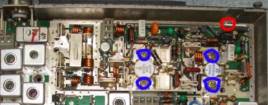
The transmitter is fairly easy to tune, and relatively stable. You will need a receiver, a frequency counter, a power meter, and a dummy load. Tune your receiver to 145.000, attach your power meter and dummy load to it, and position the frequency counter nearby. You will need the receiver and frequency counter to monitor for any signs of stability (odd noises on the transmit signal, and frequency fluctuations). Adjust potentiometer RV26 (Power output control – just above CTCSS board if fitted) to mid position. Key the radio into transmit, and carefully adjust the following three trimmers using the metal tipped trim tools: CV273 (small green one at right end)and CV289(middle top) and CV290(middle lower). These trimmers are located inside the large die cast housing at the back of the radio as shown in the photograph below (arrowed).
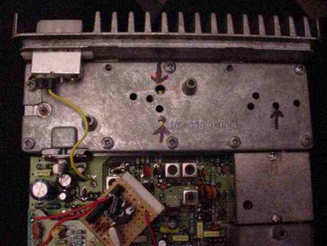
You need to have the lid on this compartment during tuning but if you prefer you can remove the lid briefly to ensure you know where they are located. You can adjust them through the holes in the lid of the compartment. I strongly recommend using plastic handled trim tools, to reduce the effect of your body’s capacitance on the tuning of the transmitter section. As you tune these trimmers, you will notice power output appear and begin to increase. Carefully continue to adjust these trimmers, one at a time for maximum power output, checking the frequency counter to ensure you are not tuning the transmitter to a spurious harmonic. As in the receiver, there is some interaction between these trimmers, so several iterations are necessary to produce peak performance and efficiency. If you feel the radio becoming very hot during this process, allow it to cool down between tuning attempts, to avoid overheating. Peak the transmit power as much as possible (without introducing instability). Once this is done, and you have a clean signal on 145.000 adjust RV26 again to set the power to between 15 and 20 Watts. (Ensure the total current drawn is not greater than 4.5 Amps – if it is, readjust the PA trimmers to bring it down to within this range.)
Step 5 – Deviation Adjustment
You will want to ensure that your deviation is suitably set for 12.5kHz channels (recommended) or 25kHz channels (obsolete). Assuming you do not have a deviation meter, set a receiver (preferably a new-ish one with 12.5kHz channel-size filters) and adjust the deviation using RV79 (situated under the CTCSS board if fitted) until the audio is a reasonable volume. Tune the receiver 12.5kHz up and shout into the microphone – there should be NO splatter onto this channel. If splatter does occur, lower the deviation level until it disappears. Step 6 – Frequency Calibration You may find that your radio is slightly off frequency. This can be corrected by adjusting the ferrite-cored trimmer L30 situated under the diode matrix board (but can be accessed without removing it). Only attempt this if you have an accurate frequency counter. Only a small adjustment (if any) should be necessary here. Adjust the trimmer carefully using a plastic tipped tool until the frequency is as accurate as possible.
That’s it! You should now have a 2m tuned T500 series Tait – you can now complete your conversion either by setting up the diode board for two channels you find useful, or proceed with the 100-channel modification, or add a 1750Hz toneburst, or even set up the CTCSS tone board (if fitted).
If you found these instructions useful, or found any errors or omissions, please email me and let me know!
Introduction
The Tait T535 VHF radio as shipped has two channels, which are set by a diode matrix board. Each channel has a transmit and receive frequency, so the diode matrix board has four ‘columns’:
Channel 1 RX Channel 2 RX Channel 1 TX Channel 2 TX
The matrix is programmed by soldering (or desoldering) adjacent pads on the board. If a solder bridge is placed across the two contacts, the link is considered closed, otherwise it is open.
A diagrammatic representation of the diode matrix board is shown below:
 Values of the diode matrix:
N9 – 128MHz
N8 – 64MHz
N7 – 32MHz
N6 – 16MHz
N5 – 8MHz
N4 – 4MHz
N3 – 2MHz
N2 – 1MHz
N1 – 500kHz
N0 – 250kHz
A5 – 200kHz
A4 – 100kHz
A3 – 50kHz
A2 – 25kHz
A1 – 12.5kHz
A0 – 6.25kHz
Calculation
Start off by soldering all the links CLOSED.
Decide on the frequencies you want to use for both channels. Subtract 21.4MHz from the receive frequencies (this is required because of the way the synthesizer works). Start subtracting the diode values listed above from your value, until you get to zero. For each diode value you ‘subtract’, desolder (ie open) that pad.
Example:
- Desired TX frequency: 145MHz
- Desired RX frequency: 145MHz
So, for the RX frequency: 145 – 21.4 = 123.6MHz TX: 128MHz + 16MHz + 1MHz = 145MHz
So: 145 – N9(128MHz) -N6(16MHz) -N2(1MHz) = 0 – Done
So, this requires diodes N9 + N6 + N2 – so, to set this frequency you would desolder (open) the pads for N9, N6 and N2.
RX frequency: 123.6MHz (adjusted by subtracting 21.4MHz) RX: 123.6MHz – N8(64MHz) -N7(32MHz) -N6(16MHz) -N5(8MHz) -N3(2MHz) – N2(1MHz) -N1(500kHz) -A4(100kHz) = 0
This requires N8 + N7 + N6 + N5 + N3 + N2 + N1 + A4, so you would desolder these pads to set the RX frequency.
The example diode matrix board shown at the top of this page is set for 145MHz TX and RX on both channels.
T555 (UHF) Diode Matrix calculations
Introduction
The Tait T555 UHF radio as shipped has two channels, which are set by a diode matrix board. Each channel has a transmit and receive frequency, so the diode matrix board has four ‘rows’:??Channel 1 RX Channel 2 RX Channel 1 TX Channel 2 TX The matrix is programmed by soldering (or desoldering) adjacent pads on the board. If a solder bridge is placed across the two contacts, the link is considered closed, otherwise it is open.
A diagrammatic representation of the diode matrix board:
Values of the diode matrix:
N9 – 409.6MHz
N8 – 204.8MHz
N7 – 102.4MHz
N6 – 51.2MHz
N5 – 25.6MHz
N4 – 12.8MHz
N3 – 6.4MHz
N2 – 3.2MHz
N1 – 1.6MHz
N0 – 800kHz
A5 – 400kHz
A4 – 200kHz
A3 – 100kHz
A2 – 50kHz
A1 – 25kHz
A0 – 12.5kHz
Calculation
Start off by soldering all the links CLOSED. Decide on the frequencies you want to use for both channels. Subtract 21.4MHz from the receive frequencies (this is required because of the way the synthesizer works). Now, work out which combination of the diode values listed above need to be added together to achieve your desired frequency.
Example:
- Desired TX frequency: 433MHz
- Desired RX frequency: 433MHz
So, for the RX frequency: 433 – 21.4 = 411.6MHz
TX: 409.6MHz + 12.8MHz + 6.4MHz + 3.2MHz + 800kHz + 200kHz = 433MHz So, this requires diodes N9 + N4 + N3 + N2 + N0 + A4 – so, to set this frequency you would desolder (open) the pads for N9, N4, N3, N2, N0 and A4.
RX frequency: 411.6MHz (adjusted by subtracting 21.4MHz) RX: 409.6 + 1.6MHz + 400kHz = 411.6MHz ?This requires N9 + N1 + A5, so you would desolder these pads to set the RX frequency.
T535 VHF CTCSS board configuration
The CTCSS board most commonly seen in these radios is labelled T500-11, and is shown in the photo below (also shown is my piggyback 1750Hz toneburst circuit:
This has two rotary multiple position switches (the two blue blocks in the middle of the photo above), one of which sets the tone for Channel 1 and the other for Channel 2. These boards are NOT capable of split tone operation – where one tone opens the squelch, but the radio transmits a different tone.
Personally, I prefer to disable CTCSS on receive, and simply have a tone on transmit. This can be accomplished by soldering a link on the CTCSS board. Close examination of the board will reveal a pair of pads labelled Hook SW (hook switch). If these are bridged together, and all the other pads are cleared, then a tone will be transmitted, but none will be required to open the squelch on receive. If my 100channel modification is fitted, the channel switch can be used to select one of two ctcss tones (or alternatively one tone, as it is possible to disable a CTCSS tone altogether on one channel.) The other links have functions not normally used by radio amateurs. e.g. LK-2 will inhibit transmit if a different tone is being received.
To set up the radio to use the desired tone, you will need another radio, which is capable of transmitting a tone. Ensure you have aligned the radio initially, as per the instructions (2m instructions ) Set your other radio to match the frequency your Tait is receiving on, and set it to transmit the desired tone. Key your transmitter. Note which channel the Tait is using (1 or 2 – view the lights on the front panel to determine this) and adjust the appropriate blue multi-position switch until the squelch opens – at this point you have the right tone. Note – the switches have a freewheeling clutch so there is no ‘stop’ at the end of travel. If you aren’t getting anywhere, try turning the switch the opposite way – each click of the switch is a different tone.
Once you have found the correct position, you can transmit using the Tait and confirm that this tone is transmitted correctly also. The potentiometer (RV447 – Level) can be used to set the deviation of the transmitted CTCSS tone).
Tait T535 Timeout Timer
The Tait T500 series radios are equipped with a transmit timeout timer, designed to prevent them from jamming a radio network, or overheating, when the PTT switch is accidentally left depressed. It is usually set to about 2 minutes (if I recall correctly). I sometimes have been known to transmit for longer than this in one go, so I decided to find out how to disable it.
Steps
-
Behind the squelch pot sits a large electrolytic capacitor (C10).
-
Just behind that, to the right (if you’re looking from the front of the radio) is a smaller electrolytic, labelled C16 by the screen print. Desolder and remove this capacitor.
That’s it – the timeout timer is now disabled.
Alternatively, increasing the value of the capacitor should give a longer timeout – the tx timeout circuit is controlled by an RC network, of which C16 is the capacitor.
Burndept Dymar
Information
Burndept Dymar
I don’t have very much info about these – they can be converted to 2m, but it’s quite a bit of work as they are originally AM sets. I think they were mainly used by some local Gas Boards. GWM radio (in Worthing, when they were in business) had bought a job lot of them and had also composed the instructions (as well as parts kits).
If you've managed to find one, and have nothing better to do, then why not 😉
They have a rather clever cradle into which they sit, which will allow disconnection of power/antenna connections simply by pulling the radio out of it, making it nice and easy to remove!
In addition, they are already 100 channel, so once the modification is completed, there is no ‘panel bashing’ required to fit thumbswitches etc..
Files
GWM Dymar instructions (from 1991!)
Prom A image (12.5kHz channels
Prom B image (12.5kHz channels